

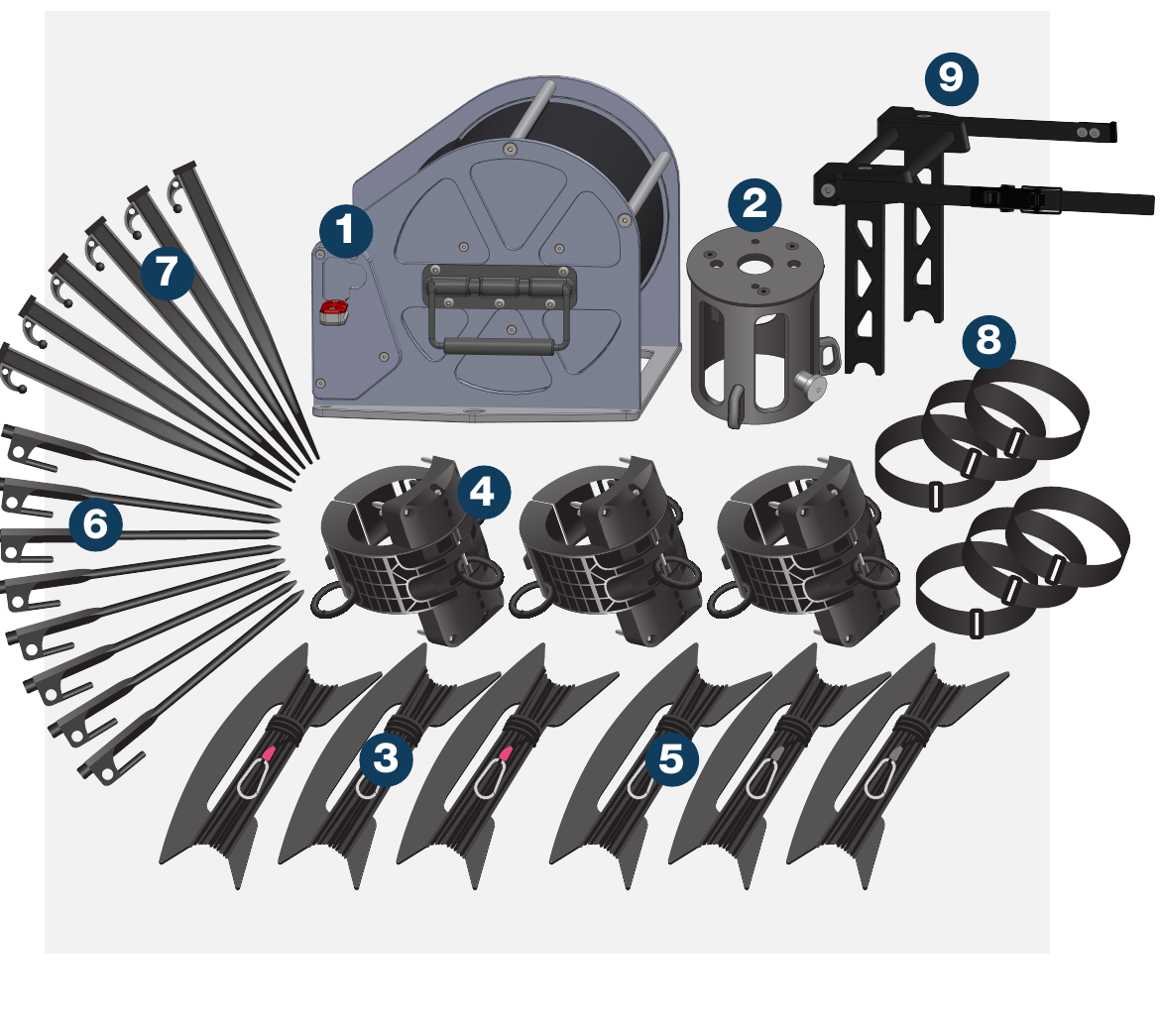
| Item | Description |
|---|---|
| 1 | 1 × 8m (26.2′) or 10m (32.8′) mast/rolacage system |
| 2 | 1 × Top Cap |
| 3 | 3 × Heavy duty top cap guy ropes (red tabs) |
| 4 | Slot locker cuffs (× 2 for 8m, × 3 for 10m) |
| 5 | 3 × Triangulated guy ropes |
| 6 | 8 × Black rock pegs |
| 7 | 6 × Soft ground pegs |
| 8 | Bag of 6 × mast straps |
| 9 | 1 × Deployment Brace |
For loads up to:
- 15kg (33lb) @ 8m (26.2′)
- 12kg (26lb) @ 10m (32.8′)
The system is rated to the load stated. The end user is responsible for ensuring the loads are securely fastened. Rolatube Technology does not accept liability or provide warranty for usage deviating from the enclosed instructions.
- Before deploying the mast please read all warnings below.
- Avoid contact with heavy and sharp objects, in storage do not stack anything on top of Rolatubes.
- Do not use the mast if there is visible damage.
- The end user must assess the suitability of the pegs provided for the intended deployment environment, and replace with more suitable products if necessary.
- Rolatube mast systems are rated for wind speeds of up to 100kph (62mph). The maximum wind rating is based on the bare mast correctly deployed and guyed. The end user or system integrator is responsible for ensuring the system is safe with the top load mounted.
- Ensure the deployment site is clear of any cables or equipment that represents an electric shock hazard.
- Do not deploy near power lines, in thunderstorms or winds exceeding 100kph (62mph).
- Do not exceed the rated top load of the mast.
- Ensure any top load is securely fastened.
- Do not allow the mast to bend.
- Ensure the deployment site is clear of any underground hazards before using pegs.
- Ensure guy ropes and pegs are secure for duration of deployment.
- Consideration must be given to the location of any cable from the top load to avoid trip hazards.
- Consideration must be given when deploying in proximity to an aircraft landing site for aircraft movement.
- Rolatube masts are only designed to function in the vertical axis.
- Deploy the mast with the slot facing away from any prevailing wind.
- Ensure mast stays vertical throughout deployment
Familiarise yourself with the operation of the mast brake system before deployment.
Applying the Brake
The BLACK brake pedal, which folds inwards for storage, must be unfolded for use. The brake is applied by fully depressing the pedal. The brake must NOT be applied directly over the holes drilled into the mast for the slot locker cuffs during either the deployment process or when deployed at partial heights.

Releasing the Brake
The RED brake release pedal also folds inwards for storage, and it too must be unfolded for use. To apply, hold the mast and lift it slightly to relieve the brake of the weight before depressing the brake release pedal. Then remove your foot from the brake release pedal and raise or lower the mast as required.

Locking the Brake
When the mast is deployed and the brake is applied the RED brake release pedal should be folded inwards to prevent accidental release.

Persons 2, 3, 4 — At guy pegs.
Position the Rolacage
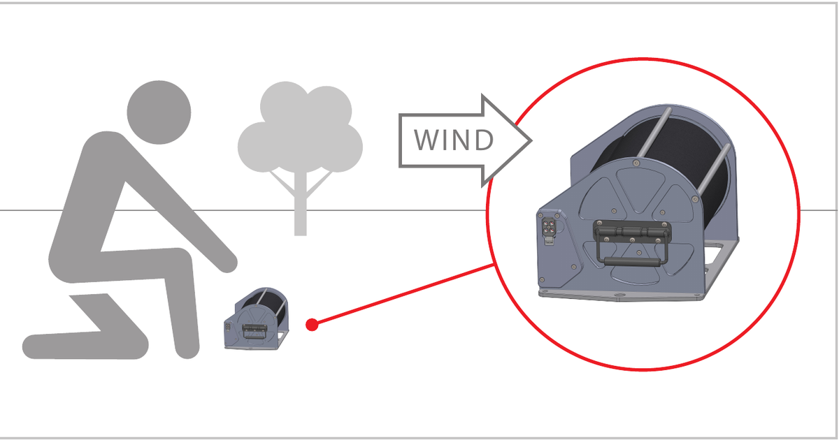
Unpack the bag and position the rolacage where you wish to deploy the mast. Orientate the rolacage so the slot of the mast will face downwind. Secure rolacage with one peg each side. Arrange the top cap, slot locker cuffs (fully opened) and payload within easy reach of the rolacage.
Raise to 1m & Pace Out Guy Ropes
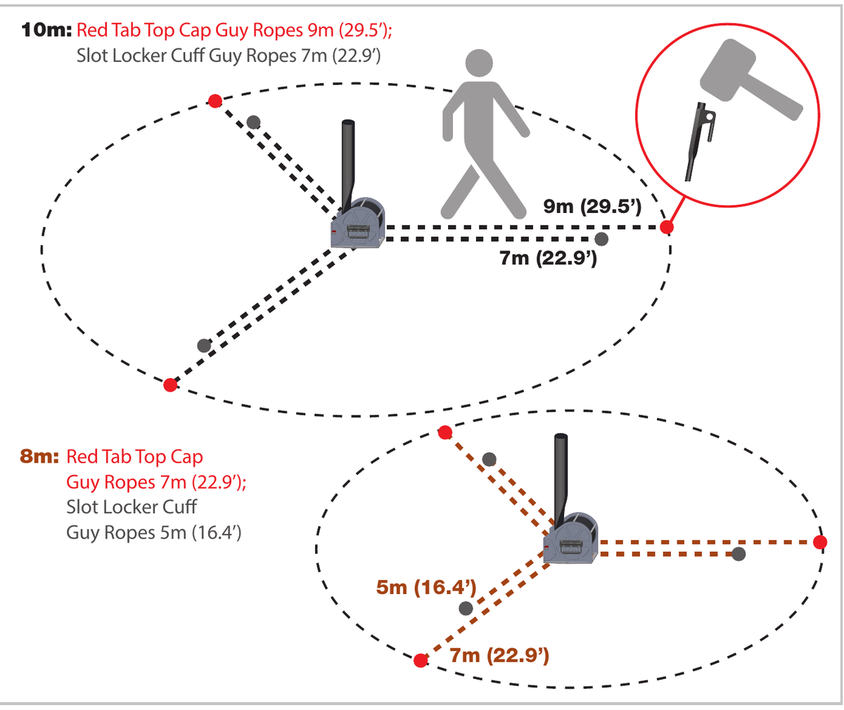
Person 1: Check the brake is released, then using the strap pull the mast up vertically to 1m and apply the brake. Whilst supporting the mast, persons 2, 3 and 4: pace out the position of the guy ropes as illustrated then hammer the pegs into the ground.
10m: Red Tab Top Cap Guy Ropes 9m (29.5′); Slot Locker Cuff Guy Ropes 7m (22.9′)
8m: Red Tab Top Cap Guy Ropes 7m (22.9′); Slot Locker Cuff Guy Ropes 5m (16.4′)
Lay Out & Connect Guy Ropes
Persons 2, 3 and 4: Unwind the top cap guy ropes (red tab). Lay out the guy ropes so the snap hooks are within easy reach of the rolacage and the ratchets at the other end of the guy ropes are attached to the outer pegs. Unwind the triangulated guy ropes, attaching the ratchet hooks to the inner pegs. Ensure the full length of all the guy ropes are deployed from the ratchets and place all snap hooks within easy reach of the rolacage. Return to the outer pegs and hold the guy ropes ready for deployment.

Fit Top Cap & Top Load
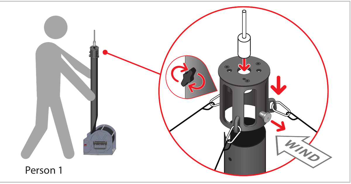
Person 1: Position top cap over tube and pull out pin. Push top cap down and release pin, then check pin is fully engaged through tube. Insert top load and rotate lock screw until tight, then connect the × 3 guy rope snap hooks to the attachment loops on the top cap.

Release Brake & Raise the Mast
Person 1: Taking the weight of the mast release the brake as per earlier guidance, then slowly raise the mast. Look upwards as the mast is being lifted and ensure it remains vertical. If the mast leans to one side, stop the deployment, apply the brake and issue instructions to tension the relevant guy rope. Persons 2, 3 and 4: Pay out the outer guy ropes maintaining even tension to keep the mast vertical.

Attach First Slot Locker Cuff
Person 1: Stop deployment when the first set of slot locker cuff holes is at chest height, and support the mast. Apply the foot brake. Attach the first of the slot locker cuffs by inserting the pins into the 4 holes drilled in the mast and pushing the cuff flush against the mast with the vertical guide bar in the slot gap. Close the hinged arms around the mast and secure with the over centre latch. Attach the triangulated guy rope snap hooks to the rings of the slot locker cuff. Persons 2, 3 & 4: Apply the necessary tension to the guy ropes to keep the mast vertical throughout.
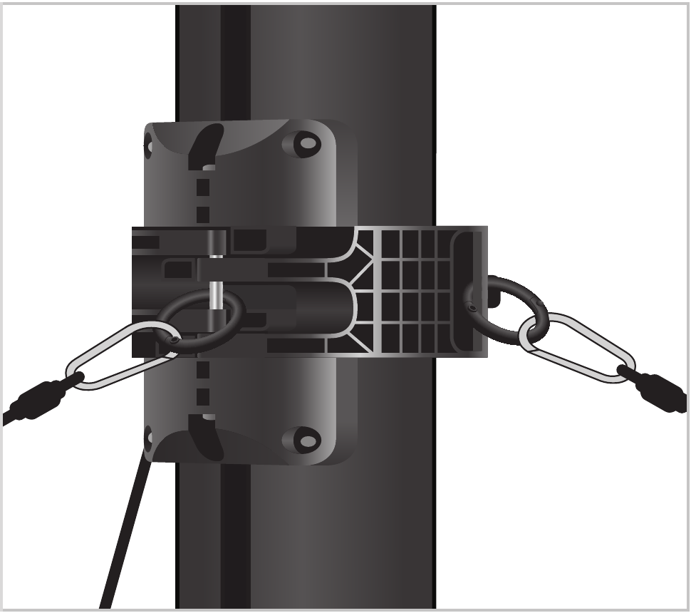
Attach Lower Slot Locker Cuff
Person 1: Release the brake and continue deployment to the lower slot locker cuff holes. Attach the lower slot locker cuff as above, attaching the final guy rope hooks. The 10m mast has a third slot locker cuff to which no guy ropes are attached. Persons 2, 3 & 4: Apply the necessary tension to the guy ropes to keep the mast vertical throughout.
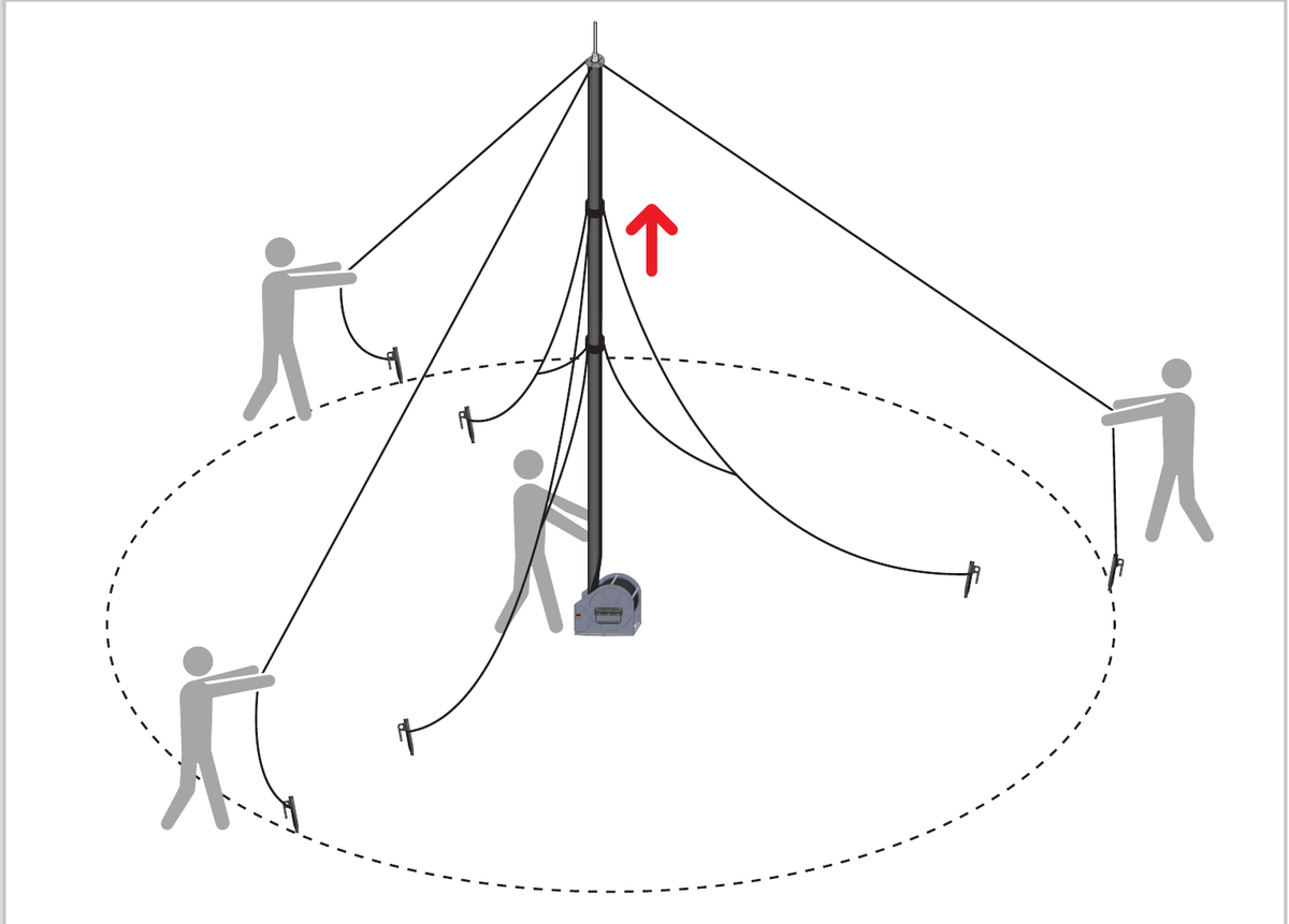
Raise to Height & Tighten Guy Ropes
Person 1: Raise the mast to the required height, or until it will unroll no further. Apply the brake and fold the brake release pedal inwards. Persons 2, 3 and 4: Tighten the outer peg guy ropes using the ratchets, ensuring the mast is vertical, then do the same with the inner peg guy ropes.

Fit Deployment Brace
Person 1: Position brace within tube slot, ensuring straps are outside of tube and legs are on roller. Secure latch around tube and confirm again legs are securely seated on roller.
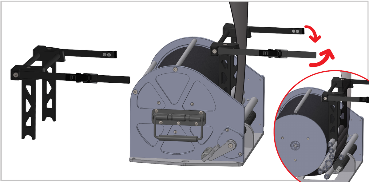
Stow the Brake Pedal
To position the brake pedal correctly for storage: 1. Fold the pedal inwards, flat against the cage. 2. Rotate the pedal so that it is fully protected by the side of the cage.

+44 (0)1590 688019
enquiries@rolatube.com
RTL Materials Ltd trading as Rolatube Technology
130 Wellworthy Road, Ampress Park, Lymington SO41 8JY, UK
Registered in England & Wales No. 3332020 • VAT Reg 706 972 317
System 100: 8m & 10m Mast / Rolacage
101mm diameter — for top loads up to 15kg (33lb) @ 8m and 12kg (26.4lb) @ 10m

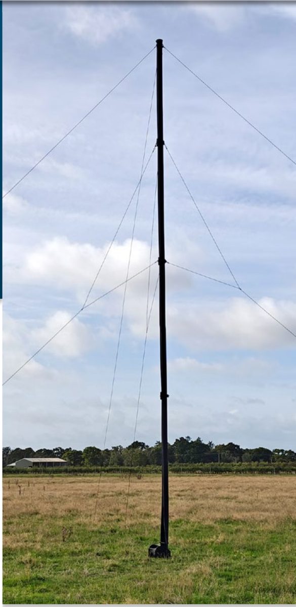

| System Name | System 100 8m Mast/Rolacage — for top loads up to 15kg (33lb) |
| Length | 8m (26.2′) (8m deployed length from Rolacage, 8.6m (28.2′) in total) |
| Mast/Rolacage Weight | 16.1kg (35.5lb) |
| System Weight* | 22.7kg (50.0lb) |
| Maximum Top Load2 | 15kg (33lb) |
| Environmental | Complies with the relevant aspects of MIL-STD-810G |
| System Name | System 100 10m Mast/Rolacage — for top loads up to 12kg (26.4lb) |
| Length | 10m (32.8′) (10m deployed length from Rolacage, 10.6m (34.8′) in total) |
| Mast/Rolacage Weight | 18.3kg (40.35lb) |
| System Weight* | 24.36kg (53.7lb) |
| Maximum Top Load2 | 12kg (26.4lb) |
| Environmental | Complies with relevant sections of MIL-STD-810G |
| Nominal Tube Diameter (Inner) | 101mm (4″) |
| Nominal Tube Arc | 355° |
| Composite Wall Thickness1 | 2.1mm (0.08″) |
| Rolled Width1 | 325mm (12.7″) |
| Typical Rolled Outer Diameter | 205mm (8″) |
| Typical Rolled Inner Diameter | 122mm (4.8″) |
| Mast/Rolacage Volume | 305.5mm × 425mm × 262.5mm (12.0″ × 16.7″ × 10.3″) |
| Packed Ancillaries Volume | 250mm × 320mm × 260mm (9.8″ × 12.5″ × 10.2″) |
| Maximum Deployed Wind speed3 | 100kph (62mph) |
System 100 Mast / Rolacage Heights at a Glance
| Variant | Deployed Height | Top Load | Mast/Rolacage Weight | System Weight* |
|---|---|---|---|---|
| 8m | 8m (26.2′) | 15kg (33lb) | 16.1kg (35.5lb) | 22.7kg (50.0lb) |
| 10m | 10m (32.8′) | 12kg (26.4lb) | 18.3kg (40.35lb) | 24.36kg (53.7lb) |
1 Average figures and subject to normal manufacturing tolerance.
2 Top load must not be exceeded. Deployment and recovery must be undertaken with the tension in all 3 top cap guy ropes being managed to ensure that the top load does not move off-centre and create bending load on the mast while top load is being elevated. This can only be achieved through 4 man operation during deployment and recovery.
3 Maximum wind loading is based on the bare mast correctly deployed and with guy pegs firmly positioned. End user or system integrator must take responsibility for deployment and ensuring that the final system is fit for purpose with regard to wind loadings once top load or other equipment is mounted.
System
| System | Part Number | NSN |
|---|---|---|
| System 100 8m Mast/rolacage Black | 956-408002-3-1 | 5985-99-753-8611 |
Components
| Component | Part Number | NSN | Qty |
|---|---|---|---|
| 8.6m 101mm (28.2′ 4″) mast (black) in Rolacage | 901-408002 | 5985-99-665-1264 | 1 |
| Top Cap | 800-500014 | 5985-99-474-9451 | 1 |
| Set of 3 × 14.5m (47.6′) Guy ropes (red tag) | 207-004123 | 4010-99-217-4531 | 1 |
| Slot Locker Cuff | 800-000129 | 5985-99-343-2412 | 2 |
| Set of 3 × 10m (32.8′) Triangulated guy ropes | 207-004120 | 4010-99-258-5281 | 1 |
| Set of 6 Mast Straps | 800-005120 | 5985-99-905-0970 | 1 |
| Steel Ground Stake 30cm black | 207-002004 | 4030-99-157-2404 | 8 |
| Soft Ground Peg | 207-002005 | 4030-99-155-8599 | 6 |
| Bag for Ancils, Black | 502-003061 | 8105-99-616-0381 | 1 |
| Deployment Brace | 800-500019 | 5985-99-598-9058 | 1 |
System
| System | Part Number | NSN |
|---|---|---|
| System 100 10m Mast/rolacage Black | 956-410002-3-1 | 5985-99-183-3519 |
Components
| Component | Part Number | NSN | Qty |
|---|---|---|---|
| 10.6m 101mm (34.8′ 4″) mast (black) in Rolacage | 901-410002 | 5985-99-969-5793 | 1 |
| Top Cap | 800-500014 | 5985-99-474-9451 | 1 |
| Set of 3 × 14.5m (47.6′) Guy ropes (red tag) | 207-004123 | 4010-99-217-4531 | 1 |
| Slot Locker Cuff | 800-000129 | 5985-99-343-2412 | 3 |
| Set of 3 × 10m (32.8′) Triangulated guy ropes | 207-004120 | 4010-99-258-5281 | 1 |
| Set of 6 Mast Straps | 800-005120 | 5985-99-905-0970 | 1 |
| Steel Ground Stake 30cm black | 207-002004 | 4030-99-157-2404 | 8 |
| Soft Ground Peg | 207-002005 | 4030-99-155-8599 | 6 |
| Bag for Ancils, Black | 502-003061 | 8105-99-616-0381 | 1 |
| Deployment Brace | 800-500019 | 5985-99-598-9058 | 1 |
| Component | Part Number | NSN |
|---|---|---|
| Central Guy Control (CGC) for System 100 8m (26.2′) and 10m (32.8′) masts | 207-300010 | 5985-99-695-4733 |
+44 (0)1590 688019
enquiries@rolatube.com • www.rolatube.com
RTL Materials Ltd trading as Rolatube Technology
130 Wellworthy Road, Ampress Park, Lymington SO41 8JY, UK
Registered in England & Wales No. 3332020 • VAT Reg 706 972 317