

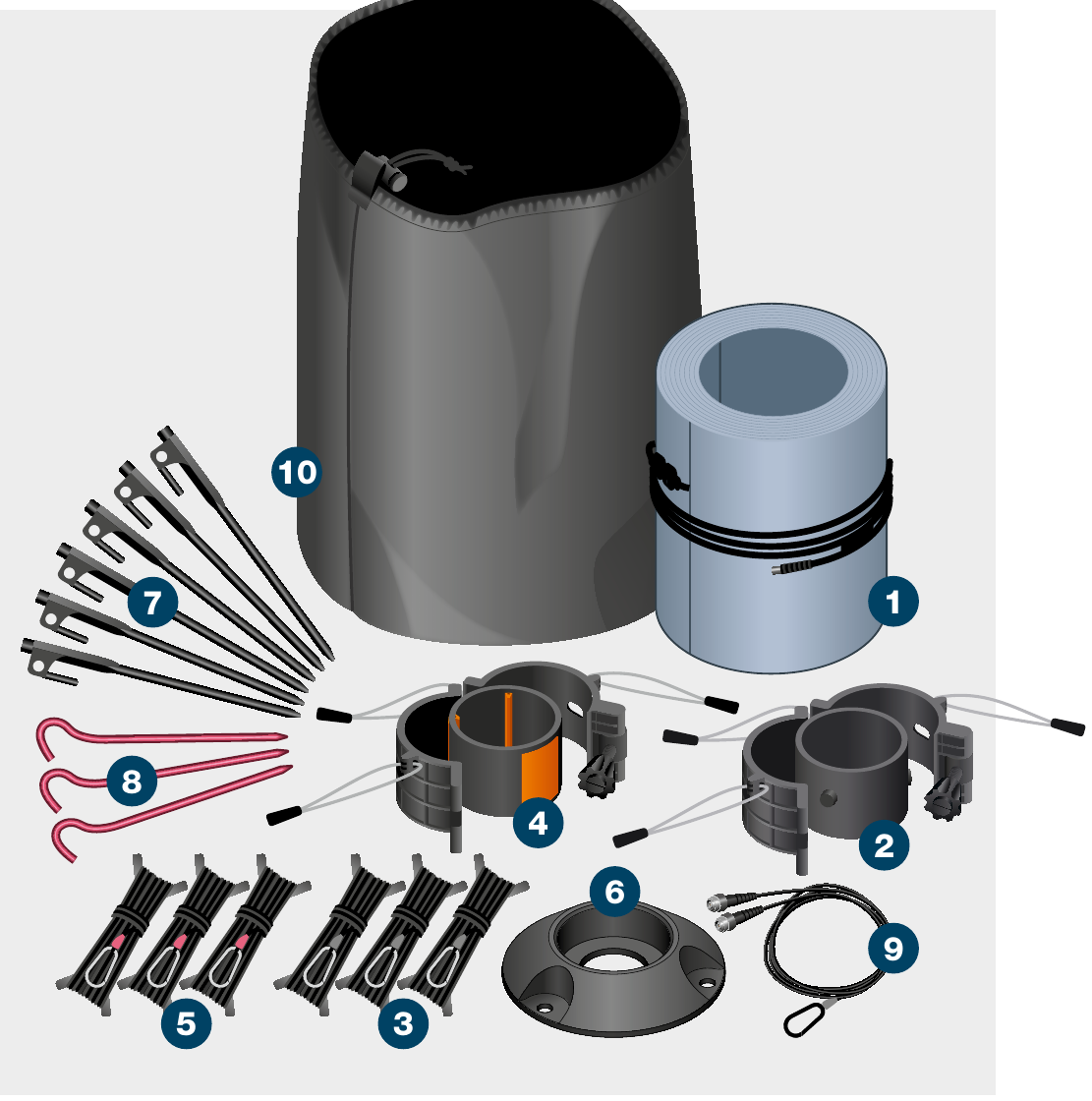
| Item | Description |
|---|---|
| 1 | 1 × 7m 76mm (22.9′ 3″) ‘RESQ’ Integrated Antenna Mast |
| 2 | 1 × Top collar |
| 3 | 3 × Top collar guy ropes |
| 4 | 1 × Lower collar |
| 5 | 3 × Lower collar guy ropes (orange tags) |
| 6 | 1 × 76mm (3″) low profile base cap |
| 7 | 6 × Black rock pegs |
| 8 | 3 × Red rock pegs |
| 9 | 1 × Connection cable with n-type (m) connector (and strain relief hook) |
| 10 | 1 × Bag |
The system is rated to the load stated. The end user is responsible for ensuring the loads are securely fastened. Rolatube Technology does not accept liability or provide warranty for usage deviating from the enclosed instructions.
- Before deploying the mast please read all warnings below.
- Avoid contact with heavy and sharp objects, in storage do not stack anything on top of Rolatubes.
- Do not use the mast if there is visible damage.
- The end user must assess the suitability of the pegs provided for the intended deployment environment, and replace with more suitable products if necessary.
- Rolatube mast systems are rated for wind speeds of up to 100kph (62mph). The maximum wind rating is based on the bare mast correctly deployed and guyed. The end user or system integrator is responsible for ensuring the system is safe with the top load mounted.
- Ensure the deployment site is clear of any cables or equipment that represents an electric shock hazard.
- Do not deploy near power lines, in thunderstorms or winds exceeding 100kph (62mph).
- Do not exceed the rated top load of the mast.
- Ensure any top load is securely fastened.
- Do not allow the mast to bend.
- Ensure the deployment site is clear of any underground hazards before using pegs.
- Ensure guy ropes and pegs are secure for duration of deployment.
- Consideration must be given to the location of any cable from the top load to avoid trip hazards.
- Consideration must be given when deploying in proximity to an aircraft landing site for aircraft movement.
- Rolatube masts are only designed to function in the vertical axis.
- Deploy the mast with the slot facing away from any prevailing wind.
Persons 2, 3 & 4 — At guy pegs: Maintaining tension during deployment to keep IAM vertical.
Position Base Cap
Person 1: Place the base cap where the IAM is to be deployed, with one peg hole facing into the wind. Secure with red base cap pegs. Place the top collar next to the base cap with the hinge facing away from the wind and the lower collar, open, nearby.

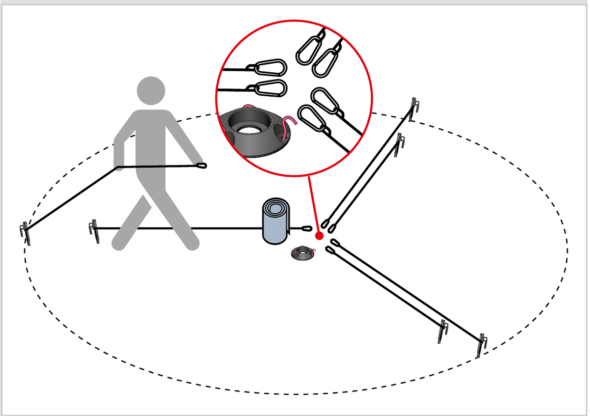
Pace Out Guy Ropes
Persons 2, 3 & 4: Using the perlon loops on the top collar for guidance, pace out the position of the various guy ropes and insert pegs into the ground. Top collar guy ropes at 4m (13.1′) and secondary cuff guy ropes at 3m (9.8′).

Connect Guy Ropes
Persons 2, 3 & 4: Unwind all guy ropes, connect to the pegs and lay the snap hooks next to the top collar, ready for connection as the IAM is deployed. Wait at the 3 outer pegs.
Unroll Until Collar Holes Visible
Person 1: Place IAM between feet, with the slot facing away from the wind, and unroll until the holes for the top collar are visible.
Fit Top Collar
Person 1: Fit top collar, with the perlon loops at the bottom, by sliding the ring up inside the IAM and inserting studs into holes, then fasten the arms around the IAM. Secure with the thumbscrew but DO NOT OVERTIGHTEN as this may damage the IAM. Clip on black guy ropes. Persons 2, 3 & 4: Maintain light tension on the guy ropes to keep IAM vertical.
Fit Lower Collar at Orange Marker
Person 1: Continue to raise IAM whilst Persons 2, 3 & 4 continue to maintain light tension on the guy ropes to keep IAM vertical. Person 1: Attach lower collar at the orange marker, with the perlon loops at the bottom, by sliding the ring up inside the IAM to the orange marker, then fasten the arms around the IAM as above. Clip on orange tabbed guy ropes and leave slack.
Slide into Base Cap
Person 1: Fully unroll the IAM and lift it carefully into the base cap with the slot facing away from the wind, whilst keeping it vertical. Persons 2, 3 & 4: Maintain light tension on guy ropes.
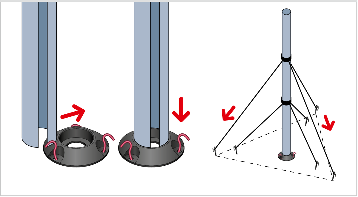
Secure All Guy Ropes
Persons 2, 3 & 4: Tighten and secure top collar guy ropes, then the remaining three guy ropes from the lower collar.
Connect & Transmit
To transmit, attach the snap hook to the retention loop then connect the cable to the RF connector on the IAM.
+44 (0)1590 688019
enquiries@rolatube.com
RTL Materials Ltd trading as Rolatube Technology
130 Wellworthy Road, Ampress Park, Lymington SO41 8JY, UK
Registered in England & Wales No. 3332020 • VAT Reg 706 972 317
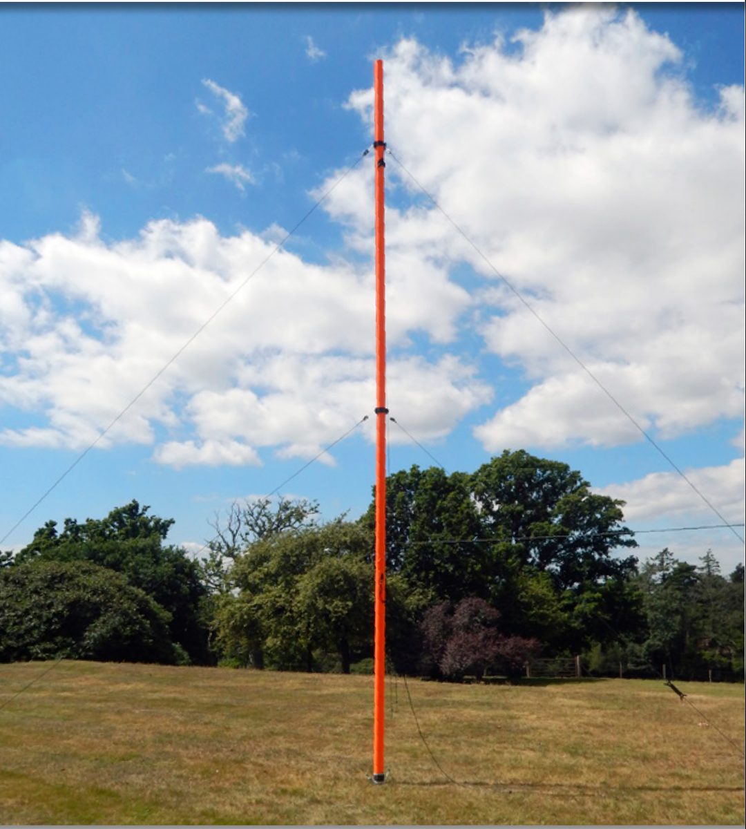
System IAM: 7m ‘RESQ’
136–175MHz Integrated Antenna Mast — vertically polarised omnidirectional dipole


| System Name | System IAM 7m ‘RESQ’ 136-175MHz |
| System Part Number |
Black: 952-307011-3-1 Orange: 952-307011-5-1 Blue: 952-307011-7-1 |
| Deployed Height | 7m (22.9′) |
| Deployed Tube ID | 76mm (3″) |
| Mast Packed / Rolled Dimensions W×H×D | 280 × 400 × 280mm (11″ × 15.7″ × 11″) |
| System Weight** | 6.2kg (13.7lb) |
| Frequency Range | 136 – 175MHz |
| Radiation Pattern | Omnidirectional |
| Antenna Format | Vertically Polarised Dipole |
| Nominal Gain | 2.2 dBi |
| VSWR | < 1.8:1 |
| Power Rating1 | 30W c.w. |
| Impedance | 50 ohms nominal |
| Connection Type | N-type(m) plug |
| System Contents |
1 × 7m 76mm (22.9′ 3″) Integrated Antenna Mast 1 × Top Collar 3 × Top Collar Guy Ropes 1 × Secondary Cuff 3 × Secondary Cuff Guy Ropes 1 × Low Profile Base Cap 6 × Black Rock Pegs 3 × Red Rock Pegs 1 × Connection Cable (with strain relief hook) 1 × Bag |
| Construct & Finish | Mast Body: PP-glass fibre composite with integrated dipole antenna External Finish: Polyester woven fabric in black, blue & orange Other colours available but MOQ will apply |
| Environmental | Operating Temp Range: -32°C to +49°C Storage Temp Range: -33°C to +71°C Waterproof & UV resistant |
1 Stated power rating is based on continuous transmit. Higher powers may be used depending on duty cycle and transmission duration protocols. Please contact your Rolatube representative to discuss your requirements before exceeding 30W.
1.0 VSWR
Rolatube 7m RESQ Integrated Antenna Mast (136 – 175 MHz) — VSWR Trace

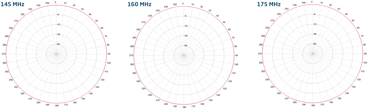
2.0 Polar Plots (Gain dB)
145 MHz • 160 MHz • 175 MHz
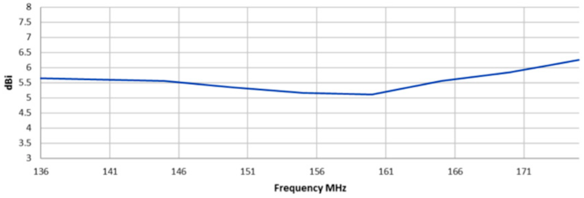
3.0 Swept Gain (dBi)
7m RESQ Swept Gain
System
| System | Part Number |
|---|---|
| System IAM 7m ‘RESQ’ 136-175MHz, Black | 952-307011-3-1 |
| System IAM 7m ‘RESQ’ 136-175MHz, Orange | 952-307011-5-1 |
| System IAM 7m ‘RESQ’ 136-175MHz, Blue | 952-307011-7-1 |
Components
| Component | Part Number | Qty |
|---|---|---|
| 7m 76mm (22.9′ 3″) ‘RESQ’ 136-175MHz IAM only, Black | 902-307011-3-0 | 1 |
| 7m 76mm (22.9′ 3″) ‘RESQ’ 136-175MHz IAM only, Orange | 902-307011-5-0 | 1 |
| 7m 76mm (22.9′ 3″) ‘RESQ’ 136-175MHz IAM only, Blue | 902-307011-7-0 | 1 |
| Top Collar with locating lugs | 800-000098 | 1 |
| Lower Cuff with orange rubber inserts | 800-000119 | 1 |
| 76mm (3″) Low profile base cap | 800-001058 | 1 |
| Set of 3 × 7.5m (26.6′) Guy ropes | 207-004108 | 1 |
| Set of 3 × 5.5m (18′) Guy ropes (orange tags) | 207-004006 | 1 |
| Connection Cable (with strain relief hook) | 207-000155 | 1 |
| Steel Ground Stake 30cm black | 207-002004 | 6 |
| Red Rock Peg | 207-002008 | 3 |
| Bag | 502-003030 | 1 |
+44 (0)1590 688019
enquiries@rolatube.com • www.rolatube.com
RTL Materials Ltd trading as Rolatube Technology
130 Wellworthy Road, Ampress Park, Lymington SO41 8JY, UK
Registered in England & Wales No. 3332020 • VAT Reg 706 972 317
Step-by-step animated deployment guide for the System IAM 7m mast.