

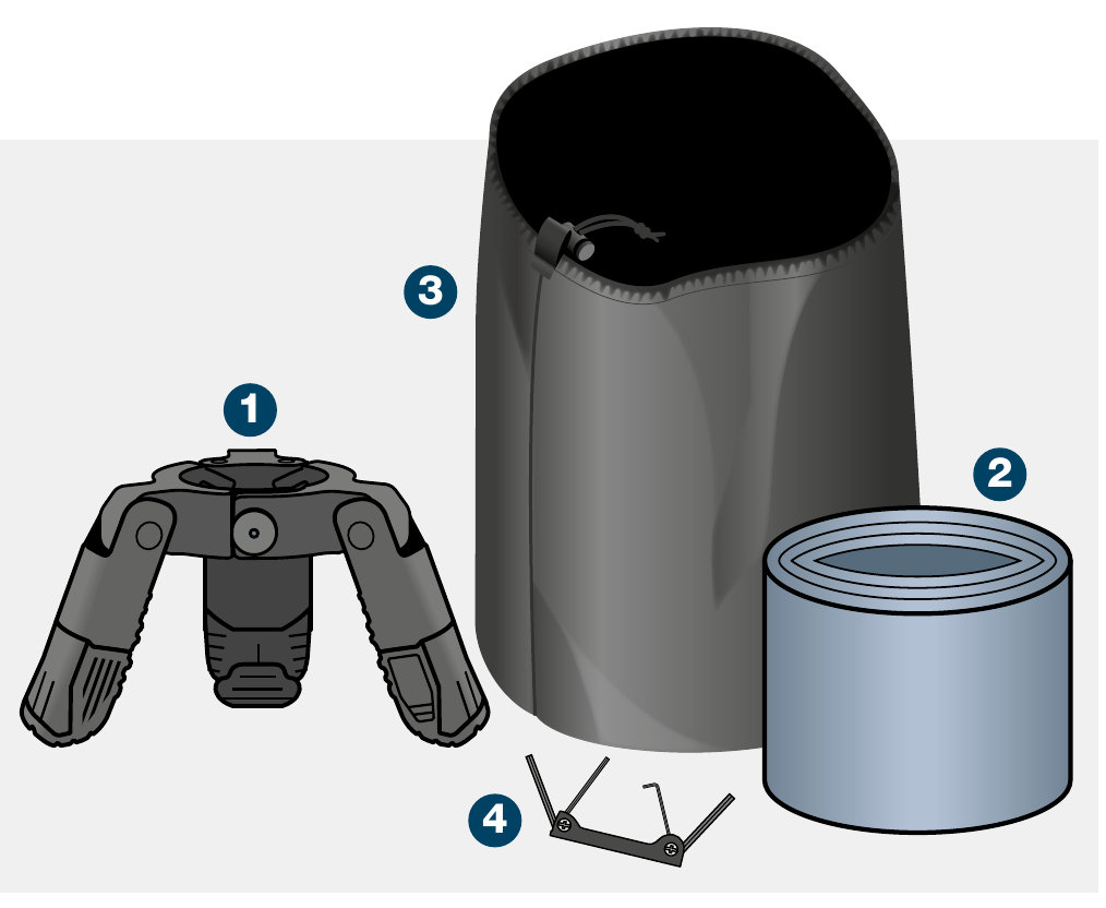
| Item | Description |
|---|---|
| 1 | 1 × Mast Support Collar |
| 2 | 3 × 1.8m Leg |
| 3 | 1 × Drawstring Bag |
| 4 | 1 × Multitool Hex Key |
Optional Accessories

| Item | Description |
|---|---|
| 5 | 3 × Pegs |
| 6 | 3 × Peg Plates |
| 7 | 3 × Weight Plates |
| 8 | 3 × Weight Bags |
| 9 | 1 × Leg Tie |
For Supporting Loads on System 75 Single Tube Masts:
8kg (17.6lb) @ 3m (9.8′)
5kg (11lb) @ 4m (13.1′)
3kg (6.6lb) @ 5m (16.4′)
For Supporting Loads on System 75 Double Tube Masts:
12kg (26.4lb) @ 3m (9.8′)
10kg (22lb) @ 4m (13.1′)
5kg (11lb) @ 5m (16.4′)
The systems are rated to the loads stated. The end user is responsible for ensuring the loads are securely fastened. Rolatube Technology does not accept liability or provide warranty for usage deviating from the enclosed instructions.
- Before deploying the mast support system please read all warnings below.
- Avoid contact with heavy and sharp objects, in storage do not stack anything on top of Rolatubes.
- Do not use the mast support system if there is visible damage.
- The end user must asses the ground conditions and the suitability of the ground attachment required for the intended deployment environment, and replace with more suitable products if necessary.
- Rolatube mast support system should only be deployed in zero or near zero wind conditions. The end user or system integrator is responsible for ensuring the system is safe with the top load correctly mounted.
- Ensure the deployment site is clear of any cables or equipment that represents an electric shock hazard.
- Do not deploy near power lines or in thunderstorms.
- Ensure the revised mast top loads are observed when using the mast support system.
- Ensure any top load is securely fastened.
- Do not allow the support legs to bend.
- Ensure the deployment site is clear of any underground hazards before using pegs.
- Ensure feet are secure for duration of deployment.
- Consideration must be given to the location of any cable from the top load to avoid trip hazards.
- Consideration must be given when deploying in proximity to an aircraft landing site for aircraft movement.
- Ensure the mast support system is fixed to the ground using pegs or weight bags.
- Ensure the deployment area is reasonably flat and clear of any debris that could impact the deployment.
Masts can only be supported unguyed by the Mast Support System indoors or in near zero wind conditions.
Attach Ground Plates
Detach feet from head unit and as required attach relevant ground plate.

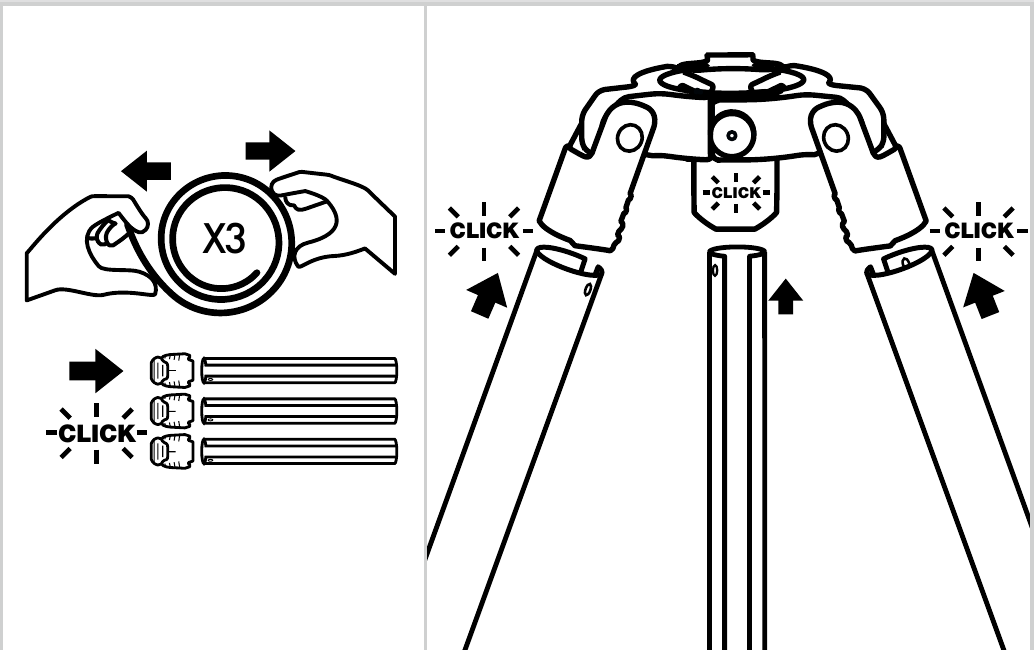
Assemble Legs
Unroll the three legs and insert securely into feet, then into the head unit.
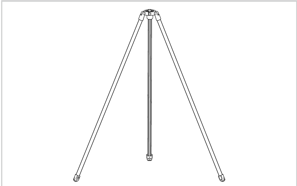
Position & Fix to Ground
Position Mast Support System at place of deployment. Position legs to make mast support collar level, then fix feet to the ground using pegs or weight bags.
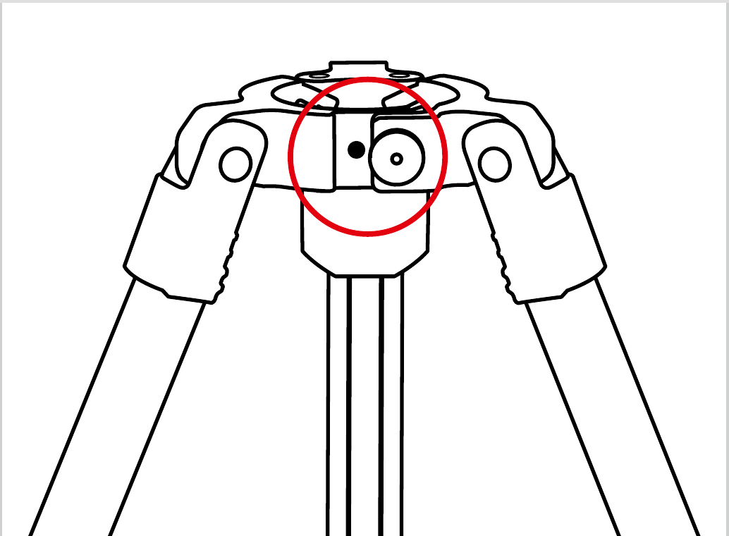
Set Collar to First Hole
Pull pin on collar, close to first hole position and release pin.
Partially Unroll Mast Through Collar
Place rolled mast between your feet to control it during deployment. Partially unroll mast through mast support collar, secure top cap and top load.

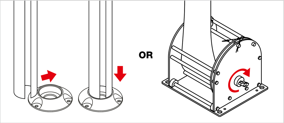
Fully Deploy & Secure
Fully deploy mast, lift into base cap ensuring the base cap is aligned with the top collar of the mast support system. Once at desired height, screw in the brake plate to secure the mast in the rolacage.
Set Collar to Second Hole
Pull pin on collar, close to second hole position and release pin. Check again the mast is vertical.

Masts can only be supported unguyed by the Mast Support System indoors or in near zero wind conditions.
Attach Ground Plates
Detach feet from head unit and as required attach relevant ground plate.
Assemble Legs
Unroll the three legs and insert securely into feet, then into the head unit.
Position & Fix to Ground
Position mast support system at place of deployment. Position legs to make mast support collar level, then fix feet to the ground using pegs or weight bags.
Open Collar Fully
Pull pin on collar and open fully.
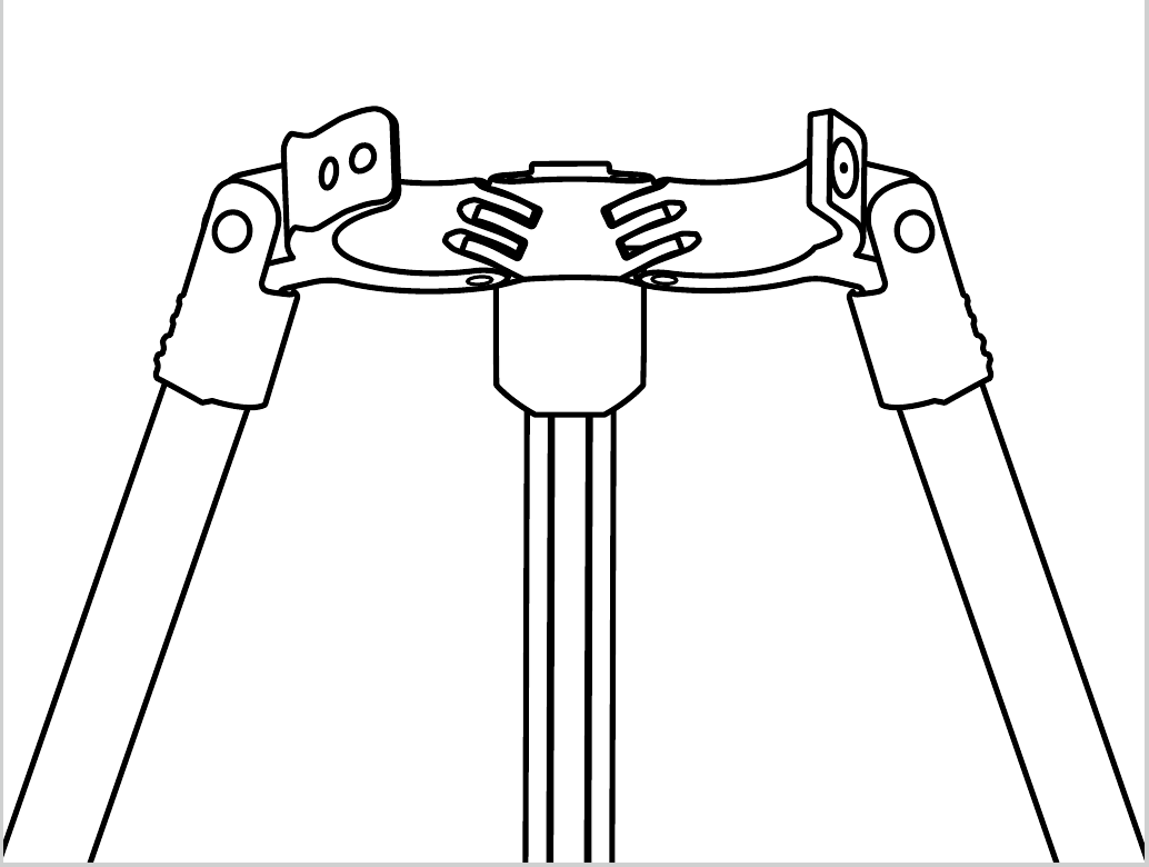
Join the Two Masts
Unroll the two masts, lie them facing slot to slot and push one into the slot of the other.

Lift Mast into Base Cap
Secure top cap and top load. Position base cap under the mast support collar. Lift mast into base cap so it is vertical in the mast support collar.

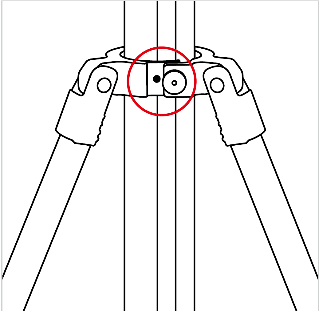
Close Collar & Check Vertical
Close the mast support collar around the mast, pull pin, align with first hole and release. Check again that mast is vertical.
+44 (0)1590 688019
enquiries@rolatube.com
RTL Materials Ltd trading as Rolatube Technology
130 Wellworthy Road, Ampress Park, Lymington SO41 8JY, UK
Registered in England & Wales No. 3332020 • VAT Reg 706 972 317
Mast Support System
For System 75 Single and Double Tube Masts (up to 5m)


| System Name | Mast Support System |
| System Part Number | 953-032-1800 |
| System Components |
1 × Mast Support Collar 3 × 1.8m Legs 1 × Drawstring Bag 1 × Multitool Hex Key |
| Accessories |
3 × Pegs 3 × Peg Plates 3 × Weight Plates 3 × Weight Bags 1 × Leg Tie |
| System Weight | 2.5kg (5.51lb) |
| Packed Dimensions | 250mm × 210mm × 240mm (9.8″ × 8.2″ × 9.4″) |
| Packed Volume | 0.013 m³ (0.44 ft³) |
| Construct & Finish |
Head unit: Aluminium, POM-C and PC/ABS Rolatube Leg: PP-Glass Fiber composite Allen Key Multitool: Aluminium and Steel Drawstring Bag: Nylon |
| Environmental | Compliant with the relevant sections of Mill-STD-810H |
| Wind speed | Zero or near zero (unguyed) |
System 75 Single Tube Masts
| Mast Height | Max. Top Load |
|---|---|
| 3m Single Tube Mast (with or without Rolacage) | 8kg (17.6lb) |
| 4m Single Tube Mast (with or without Rolacage) | 5kg (11lb) |
| 5m Single Tube Mast (with or without Rolacage) | 3kg (6.6lb) |
System 75 Double Tube Masts
| Mast Height | Max. Top Load |
|---|---|
| 3m Double Tube Mast | 12kg (26.4lb) |
| 4m Double Tube Mast | 10kg (22lb) |
| 5m Double Tube Mast | 5kg (11lb) |
System
| System | Rolatube Part Number | NSN |
|---|---|---|
| Mast Support System | 953-032-1800 | NSN Pending |
Components
| Component | Rolatube Part Number | NSN | Qty |
|---|---|---|---|
| Mast Support Collar | 800-500033 | NSN Pending | 1 |
| 1.8m Leg | 850-321800 | NSN Pending | 3 |
| Multitool Hex Key | 403-000128 | 5120-99-275-5930 | 1 |
| Drawstring Bag | 502-003021 | 8105-99-259-8325 | 1 |
Accessories
| Component | Rolatube Part Number | NSN | Qty |
|---|---|---|---|
| Peg Plate | 800-008100 | 5985-99226-8166 | 3 |
| Peg | 207-002009 | 4030-99-549-8946 | 3 |
| Weight Plate | 800-008101 | NSN Pending | 3 |
| Weight Bag | 502-003059 | NSN Pending | 3 |
| Leg Tie | 800-500084 | NSN Pending | 1 |
+44 (0)1590 688019
enquiries@rolatube.com • www.rolatube.com
RTL Materials Ltd trading as Rolatube Technology
130 Wellworthy Road, Ampress Park, Lymington SO41 8JY, UK
Registered in England & Wales No. 3332020 • VAT Reg 706 972 317