

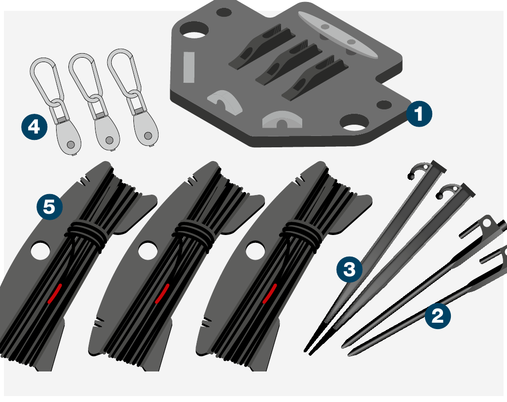
| Item | Description |
|---|---|
| 1 | 1 × CGC base plate |
| 2 | 2 × Black rock pegs |
| 3 | 2 × Soft ground pegs |
| 4 | 3 × Pulleys |
| 5 | 3 × CGC guy ropes *i |
*i Length will depend on height of mast
The CGC system includes top cap guy ropes to replace those supplied with the mast system. General mast deployment (as described in the specific mast user guide) should be followed but with the CGC system substituted for the top cap guy ropes.
The system is rated to the load stated. The end user is responsible for ensuring the loads are securely fastened. Rolatube Technology does not accept liability or provide warranty for usage deviating from the enclosed instructions.
- Before deploying the mast please read all warnings below.
- Avoid contact with heavy and sharp objects, in storage do not stack anything on top of Rolatubes.
- Do not use the mast if there is visible damage.
- The end user must assess the suitability of the pegs provided for the intended deployment environment, and replace with more suitable products if necessary.
- Rolatube mast systems are rated for wind speeds of up to 100kph (62mph). The maximum wind rating is based on the bare mast correctly deployed and guyed. The end user or system integrator is responsible for ensuring the system is safe with the top load mounted.
- Ensure the deployment site is clear of any cables or equipment that represents an electric shock hazard.
- Do not deploy near power lines, in thunderstorms or winds exceeding 100kph (62mph).
- Do not exceed the rated top load of the mast.
- Ensure any top load is securely fastened.
- Do not allow the mast to bend.
- Ensure the deployment site is clear of any underground hazards before using pegs.
- Ensure guy ropes and pegs are secure for duration of deployment.
- Consideration must be given to the location of any cable from the top load to avoid trip hazards.
- Consideration must be given when deploying in proximity to an aircraft landing site for aircraft movement.
- Rolatube masts are only designed to function in the vertical axis.
- Deploy the mast with the slot facing away from any prevailing wind.
Mast operator — deploys the mast according to the mast User Guide.
This sequence applies to both the System 75 and System 100 CGC — both User Guides follow the same seven numbered steps. System 100 differences are flagged where they apply.
Unpack & Clip on Pulleys
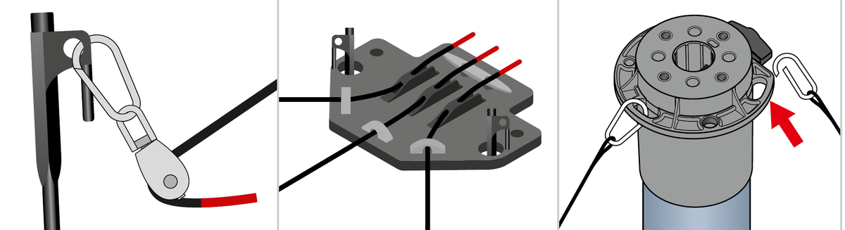
Unpack the CGC system laying out all components on the ground. Clip the three guy rope pulleys to the chosen pegs from your mast system.
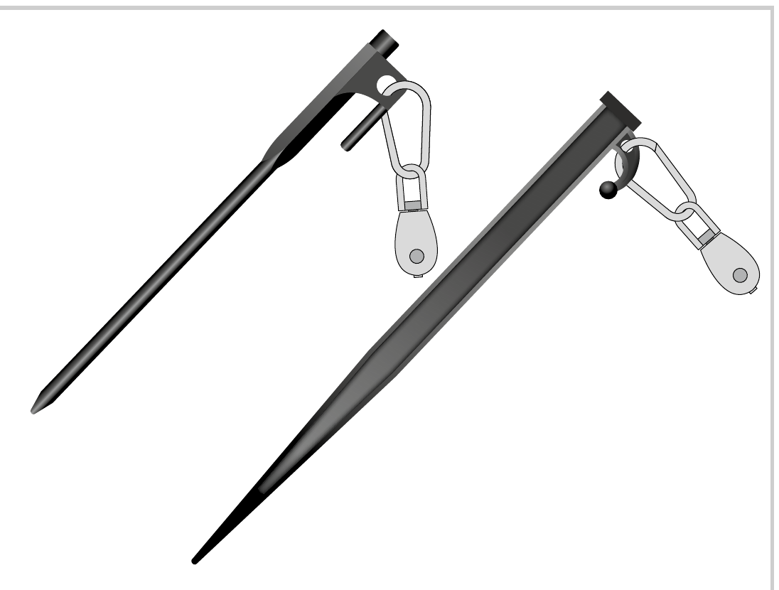
Position the Pegs
Position these pegs according to the instructions within the User Guide for the mast system.
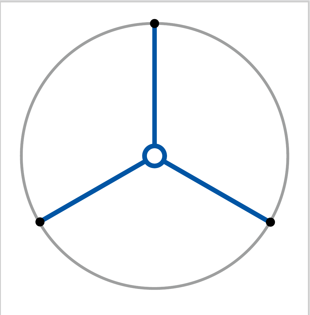
Position the CGC Base Plate
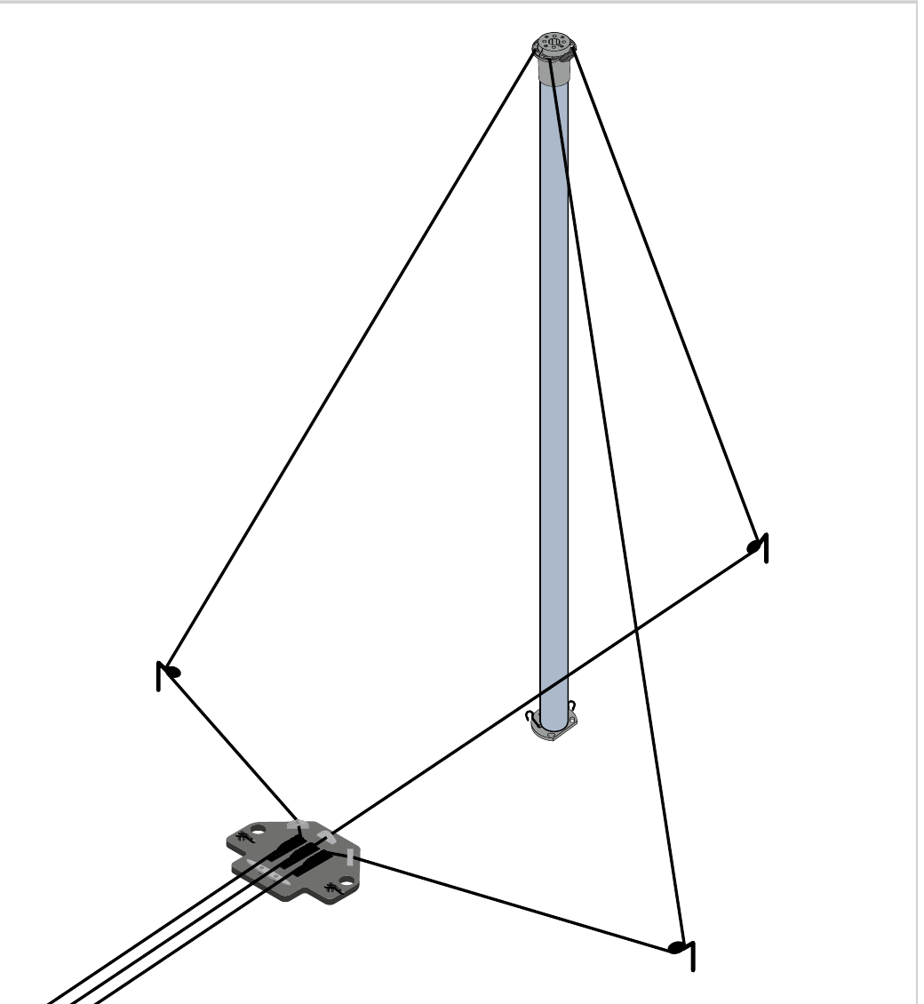
Position the CGC base plate off centre as shown, ensuring it’s aligned with the far peg. Once positioned correctly secure with appropriate ground pegs.
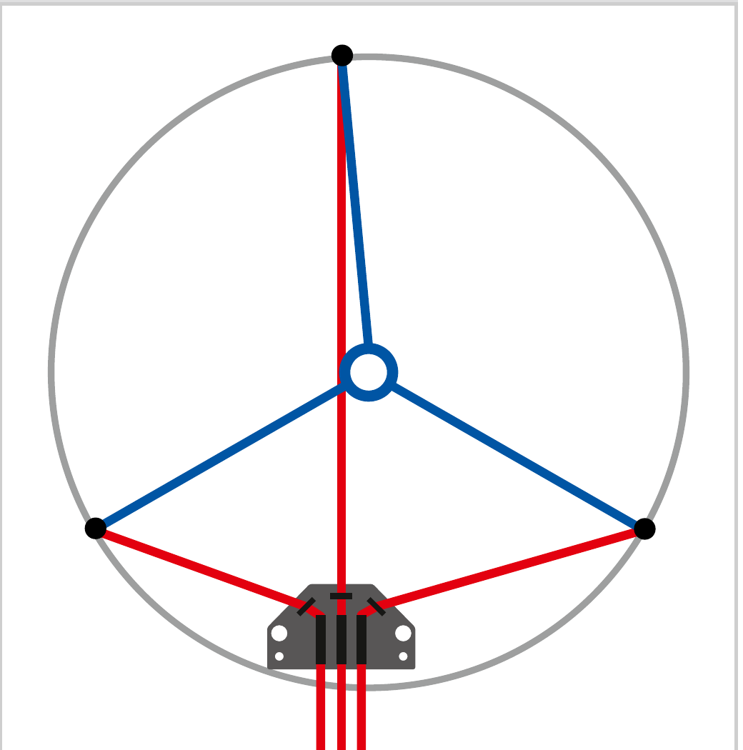
Secondary Cuff Guy Ropes
Note: If your mast system has a secondary cuff with guy ropes, place those guy ropes and their pegs according to the instructions in the mast User Guide before continuing with these instructions. On System 100 this step always applies — the secondary cuff guy ropes are always fitted.
You will need to ensure:
- the guy ropes from the top cap to the CGC ground peg pulleys lie over the top of the laid out secondary cuff guy ropes;
- the guy ropes running from the pulleys to the CGC base plate lie under the laid out secondary cuff guy ropes, and themselves.
Reeve the Guy Ropes
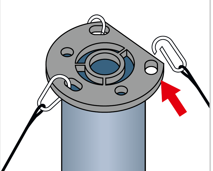
Run the red end of the three guy ropes from the base of the undeployed mast, through the pulleys from the top as illustrated and through the CGC base plate. Clip the other ends to the top cap and take up slack so the mast can be supported as it is raised.
Control the Guys During Deployment
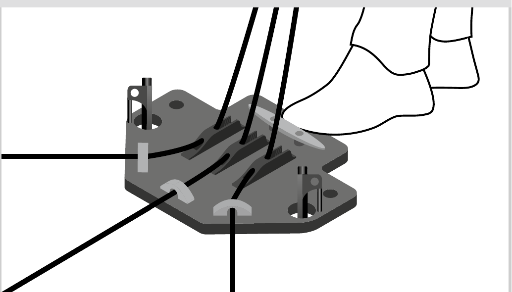
One person now controls the three top cap guy ropes through the CGC, whilst another deploys the mast according to the mast User Guide. The CGC is controlled by keeping one foot on the CGC base plate and maintaining tension on all three guy ropes whilst feeding them out. They can be secured at any time, and at the end of deployment, by securing them in the cleats.
The three guy ropes will deploy at different rates. The CGC operator should ensure that the mast stays vertical by halting deployment and adjusting guy tension when required.
Check and Secure Once Deployed
Once deployed check the guy ropes are secure within cleats and secured around horn cleat in X pattern.
+44 (0)1590 688019
enquiries@rolatube.com
RTL Materials Ltd trading as Rolatube Technology
130 Wellworthy Road, Ampress Park, Lymington SO41 8JY, UK
Registered in England & Wales No. 3332020 • VAT Reg 706 972 317
Central Guy Control (CGC)
Deployment aid for System 75 and System 100 Rolatube mast systems

For use with System 75 and System 100 Rolatube mast systems. Enables one person to control three guy ropes to provide support to the mast during deployment, thus reducing the number of personnel required by 2.

| Product Name | CGC for System 75 3m (9.8′) & 4m (13.1′) mast |
| Part Number | 207-300004 |
| NSN | 5985-99-269-4942 |
| Compatible Mast Heights | 3m (9.8′) & 4m (13.1′) System 75 |
| Product Name | CGC for System 75 5m (16.4′) & 7m (22.9′) mast |
| Part Number | 207-300007 |
| NSN | 5985-99-298-0087 |
| Compatible Mast Heights | 5m (16.4′) & 7m (22.9′) System 75 |
| Product Name | CGC for System 100 8m (26.2′) & 10m (32.8′) mast |
| Part Number | 207-300010 |
| NSN | 5985-99-695-4733 |
| Compatible Mast Heights | 8m (26.2′) & 10m (32.8′) System 100 |
| Max Top Load | 5kg (11lb) |
Materials, Weights & Dimensions (all variants)
| Item | Material | Weight |
|---|---|---|
| Base Plate | Thermoplastic | 0.58kg (1.3lbs) |
| Guy Tidies | Thermoplastic | Set of 3 1.93kg (4.3lbs)* |
| Guy Ropes | Braided Polyester | — |
| Black Rock Pegs | Steel | ×2 0.48kg |
| Soft Ground Pegs | Thermoplastic | ×2 0.08kg |
| Pulleys | Stainless Steel | 3 pulleys 0.17kg (0.4lbs) |
| Total weight | 3.24kg |
All CGC Variants at a Glance
| Variant | Mast Heights | Part Number | NSN |
|---|---|---|---|
| System 75 | 3m (9.8′) & 4m (13.1′) | 207-300004 | 5985-99-269-4942 |
| System 75 | 5m (16.4′) & 7m (22.9′) | 207-300007 | 5985-99-298-0087 |
| System 100 | 8m (26.2′) & 10m (32.8′) | 207-300010 | 5985-99-695-4733 |
System
| System | Part Number | NSN |
|---|---|---|
| CGC for System 75 3m (9.8′) & 4m (13.1′) mast | 207-300004 | 5985-99-269-4942 |
| CGC for System 75 5m (16.4′) & 7m (22.9′) mast | 207-300007 | 5985-99-298-0087 |
| CGC for System 100 8m (26.2′) & 10m (32.8′) mast | 207-300010 | 5985-99-695-4733 |
Components
| Component | Material | Qty |
|---|---|---|
| CGC base plate | Thermoplastic | 1 |
| Black rock pegs | Steel | 2 |
| Soft ground pegs | Thermoplastic | 2 |
| Pulleys | Stainless Steel | 3 |
| CGC guy ropes* | Braided Polyester | 3 |
+44 (0)1590 688019
enquiries@rolatube.com • www.rolatube.com
RTL Materials Ltd trading as Rolatube Technology
130 Wellworthy Road, Ampress Park, Lymington SO41 8JY, UK
Registered in England & Wales No. 3332020 • VAT Reg 706 972 317