
| Item | Description |
|---|---|
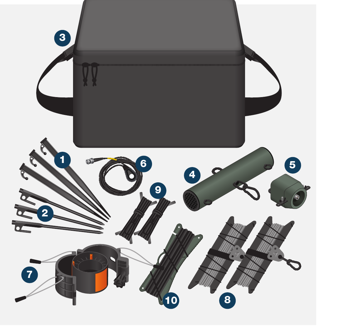
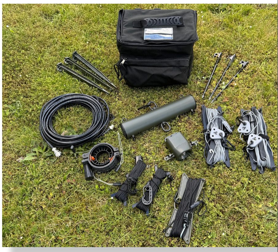
| 1 | 3 × Black hard ground pegs |
| 2 | 3 × Soft ground pegs |
| 3 | 1 × System bag |
| 4 | 1 × Resistor tube |
| 5 | 1 × 150W Balun |
| 6 | 1 × Radio connection cable (15.24m) (50’) |
| 7 | 1 × Secondary Cuff |
| 8 | 2 × Dipole antenna legs |
| 9 | 2 × Dipole guy rope extensions |
| 10 | 1 × Hoist rope |
The system is rated to the load stated. The end user is responsible for ensuring the loads are securely fastened. Rolatube Technology does not accept liability or provide warranty for usage deviating from the enclosed instructions.
- Before deploying the mast please read all warnings below.
- Avoid contact with heavy and sharp objects, in storage do not stack anything on top of Rolatubes.
- Do not use the mast if there is visible damage.
- The end user must assess the suitability of the pegs provided for the intended deployment environment, and replace with more suitable products if necessary.
- Rolatube mast systems are rated for wind speeds of up to 100kph (62mph). The maximum wind rating is based on the bare mast correctly deployed and guyed. The end user or system integrator is responsible for ensuring the system is safe with the top load mounted.
- Ensure the deployment site is clear of any cables or equipment that represents an electric shock hazard.
- Do not deploy near power lines, in thunderstorms or winds exceeding 100kph (62mph).
- Do not exceed the rated top load of the mast.
- Ensure any top load is securely fastened.
- Do not allow the mast to bend.
- Ensure the deployment site is clear of any underground hazards before using pegs.
- Ensure guy ropes and pegs are secure for duration of deployment.
- Consideration must be given to the location of any cable from the top load to avoid trip hazards.
- Consideration must be given when deploying in proximity to an aircraft landing site for aircraft movement.
- Rolatube masts are only designed to function in the vertical axis.
- Deploy the mast with the slot facing away from any prevailing wind.
Attach Clip to Top Cap
During the mast deployment either fit the clip to the top cap and feed the antenna hoist rope through the clip on the top cap.
Secure the hoist rope to prevent it being raised with the mast.
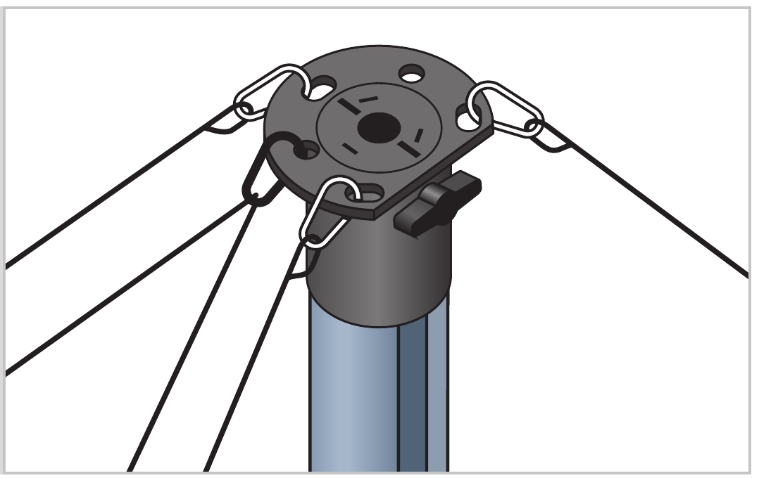
Fit the Secondary Cuff
Fit the secondary cuff to the mast at the desired height and secure in place using the thumb screw. Attach the clip to the lanyard. Feed the hoist rope through the clip on the secondary cuff.
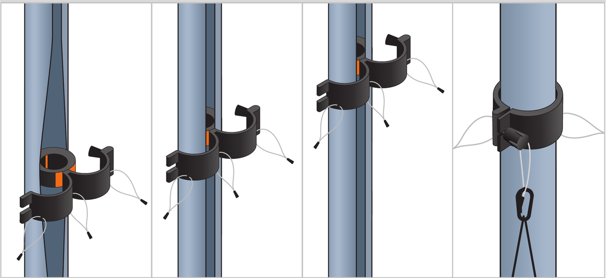
While fitting a slot locker cuff, attach the clip to one of the rings. Feed the hoist rope through the clip on the slot locker cuff.

Continue Mast Deployment
Continue deployment of the mast as per the mast user guide.
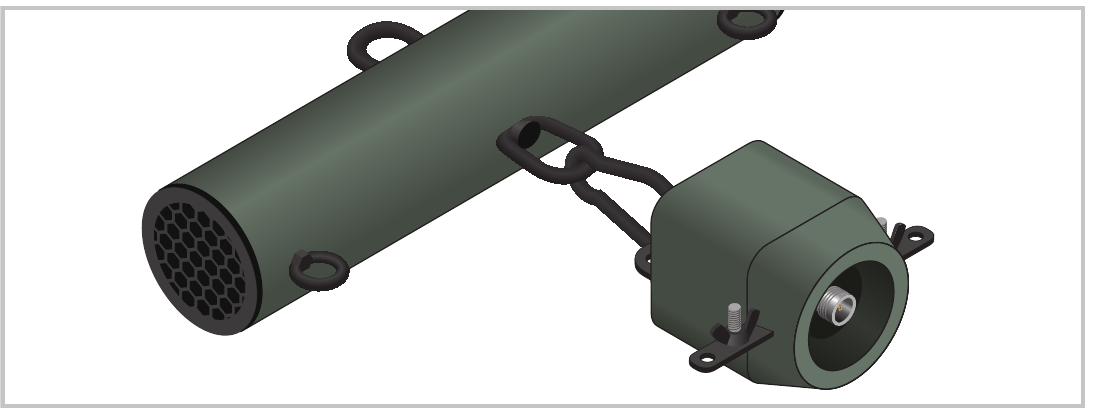
Connect Balun to Resistor Tube
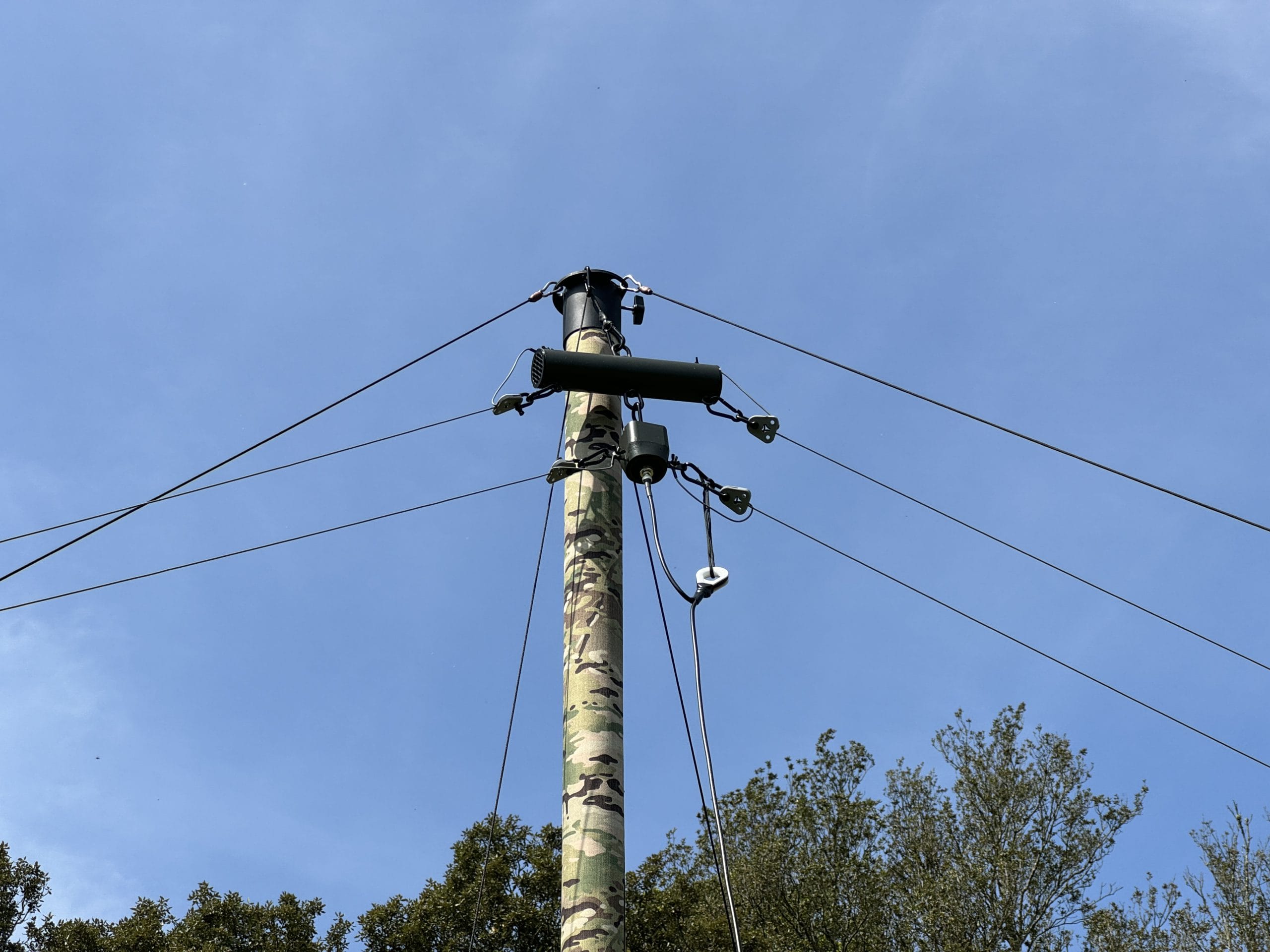
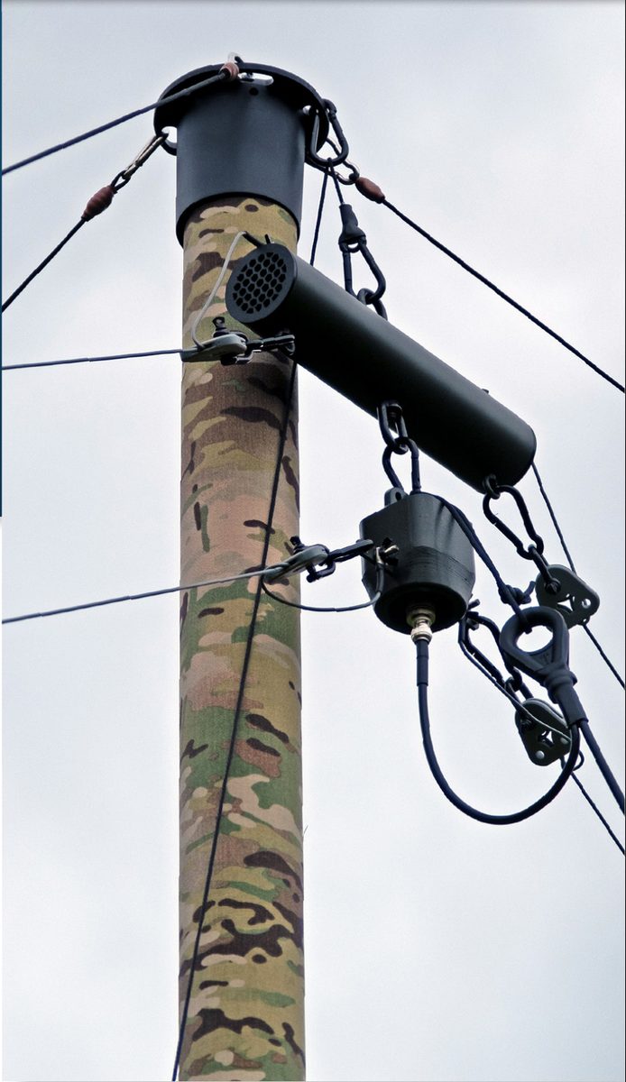
Connect the balun to the resistor tube using the snap hook.
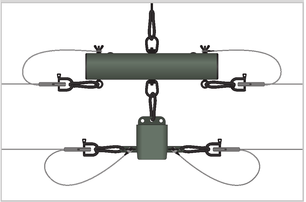
Connect Hoist Rope & Dipole Legs
Connect the hoist rope to the top of the resistor tube using the snap hook. Unroll the dipole antenna legs and connect to the resistor tube and balun. Ensure all four strain relief snap hooks are correctly fitted.
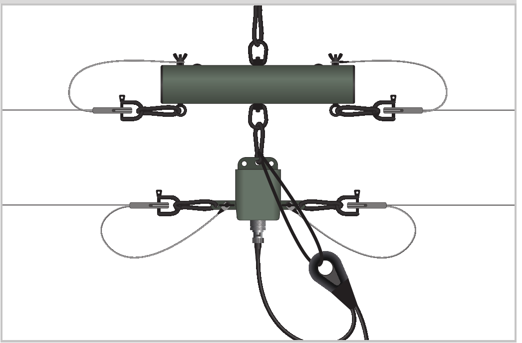
Connect the Radio Cable
Connect the radio cable to the balun and ensure its strain relief cable is attached to the snap hook on the top of the balun.
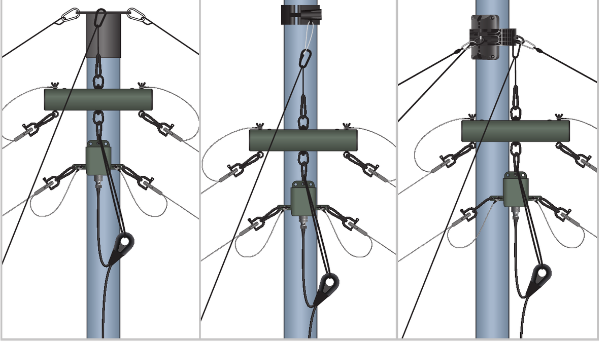
Raise the Antenna Assembly
Raise the antenna assembly using the hoist rope to the desired height. Secure the hoist rope to the base cap or ground using a peg.
Peg Out the Dipoles
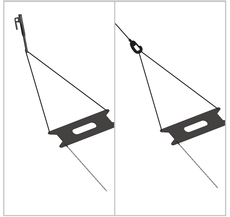
Use the pegs to secure the dipoles in position. If required attach the extension guy ropes to the dipoles and peg and tension in the usual way.
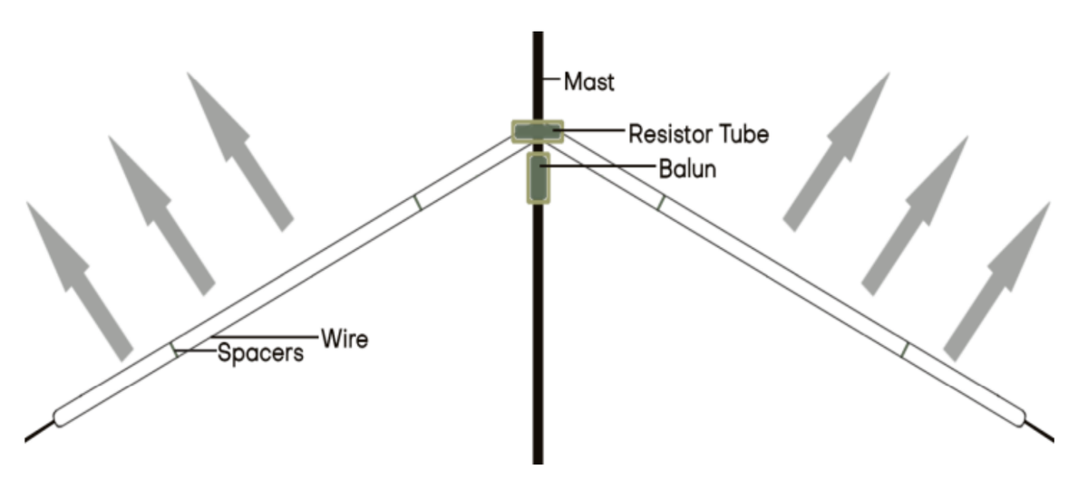
Inverted V
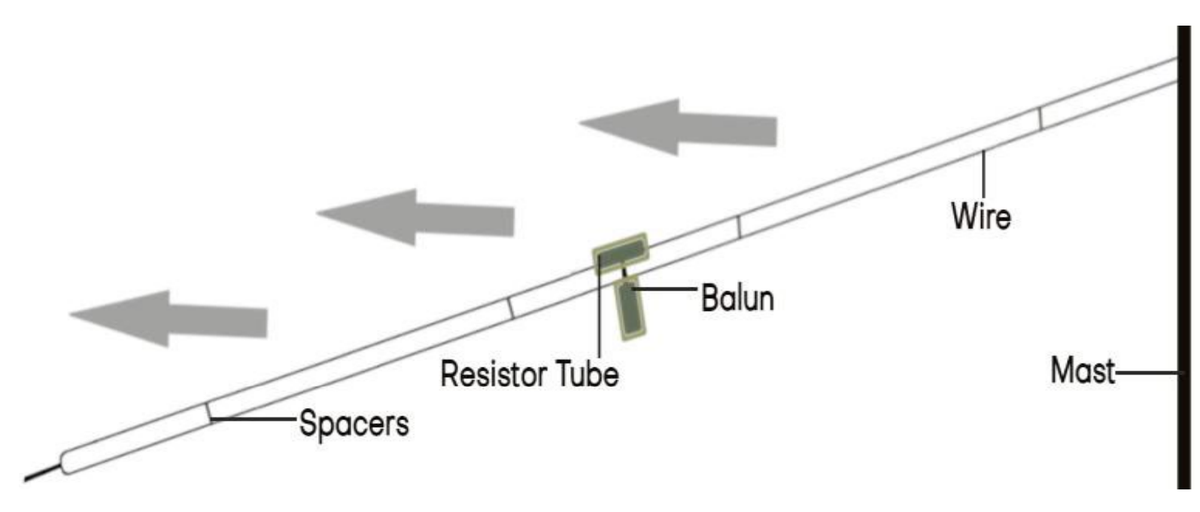
Slope
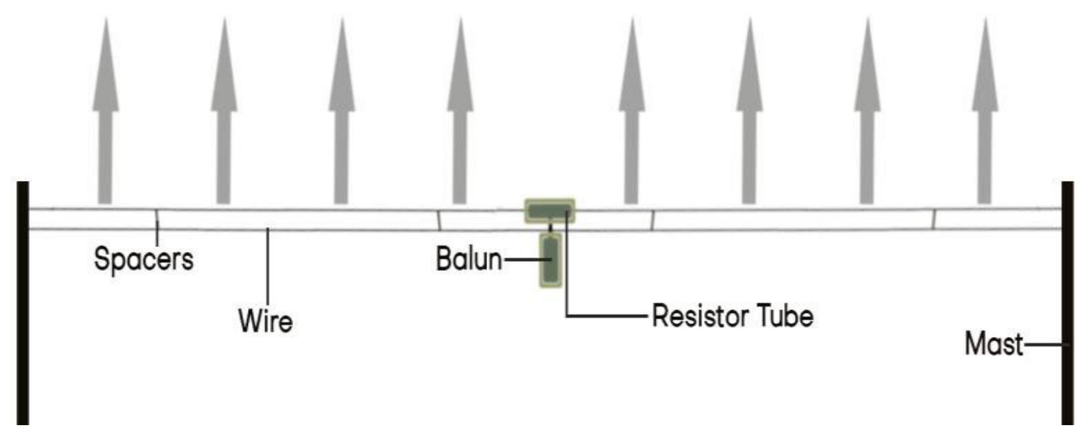
Horizontal
+44 (0)1590 688019
enquiries@rolatube.com
RTL Materials Ltd trading as Rolatube Technology
130 Wellworthy Road, Ampress Park, Lymington SO41 8JY, UK
Registered in England & Wales No. 3332020 • VAT Reg 706 972 317
HF Antenna Kit
1.8–30MHz horizontally polarized folded dipole — mast-mounted, 150W

| Description | Horizontally Polarized Folded Dipole |
| Frequency Range | 1.8 – 30MHz |
| Power Rating | 150W |
| VSWR | 1.5 : 1 Maximum |
| Impedance | 50 Ohms nominal |
| Radiation Pattern | Omnidirectional |
| RF Connector | BNC male to N Type male |
| RF Coaxial | RG8X 15.24m (50′ nominal) |
| System Weight | 4.7kg (10.4lbs) |
| Deployed Width | Up to 16.76m (55′ nominal) |
| Deployed Height | Up to 10m (32′ 9″ nominal) |
| Antenna Weight1 | 3.0kg (6.6lbs) |
| Environmental | Complies with the relevant aspects of MIL-STD-810G. |
| Compatibility | System 75 5m Single Tube Mast1, System IAM 7m, System 100 |
System
| System | Part Number | NSN | Qty |
|---|---|---|---|
| HF Antenna Kit | 207-180001 | 5985-99-356-4997 | 1 |
HF Antenna Kit Component List
| Component | Part Number | NSN | Qty |
|---|---|---|---|
| HF Antenna | 702-000001 | NSN Pending | 1 |
| Secondary Cuff for System 75 | 800-000119 | 5985-99-291-1726 | 1 |
| Small System Bag | 502-003062 | 8105-99-753-0838 | 1 |
HF Antenna Component List
| Component | Part Number | NSN | Qty |
|---|---|---|---|
| HF Antenna Resistor Tube | 703-000001 | NSN Pending | 1 |
| Balun HF 150W 2-30MHz | 703-000002 | NSN Pending | 1 |
| HF Antenna Dipole | 703-000003 | NSN Pending | 2 |
| RF Coaxial Cable (15.24m, 50’) | 703-000005 | NSN Pending | 1 |
| HF Antenna Guy Rope | 703-000006 | NSN Pending | 2 |
| Hoist Rope with Ratchet | 703-000007 | NSN Pending | 1 |
| Black Ground Stake 30cm | 207-002004 | 4030-99-157-2404 | 3 |
| Green Soft Ground Peg | 207-002005 | 4030-99-155-8599 | 3 |
+44 (0)1590 688019
enquiries@rolatube.com • www.rolatube.com
RTL Materials Ltd trading as Rolatube Technology
130 Wellworthy Road, Ampress Park, Lymington SO41 8JY, UK
Registered in England & Wales No. 3332020 • VAT Reg 706 972 317