

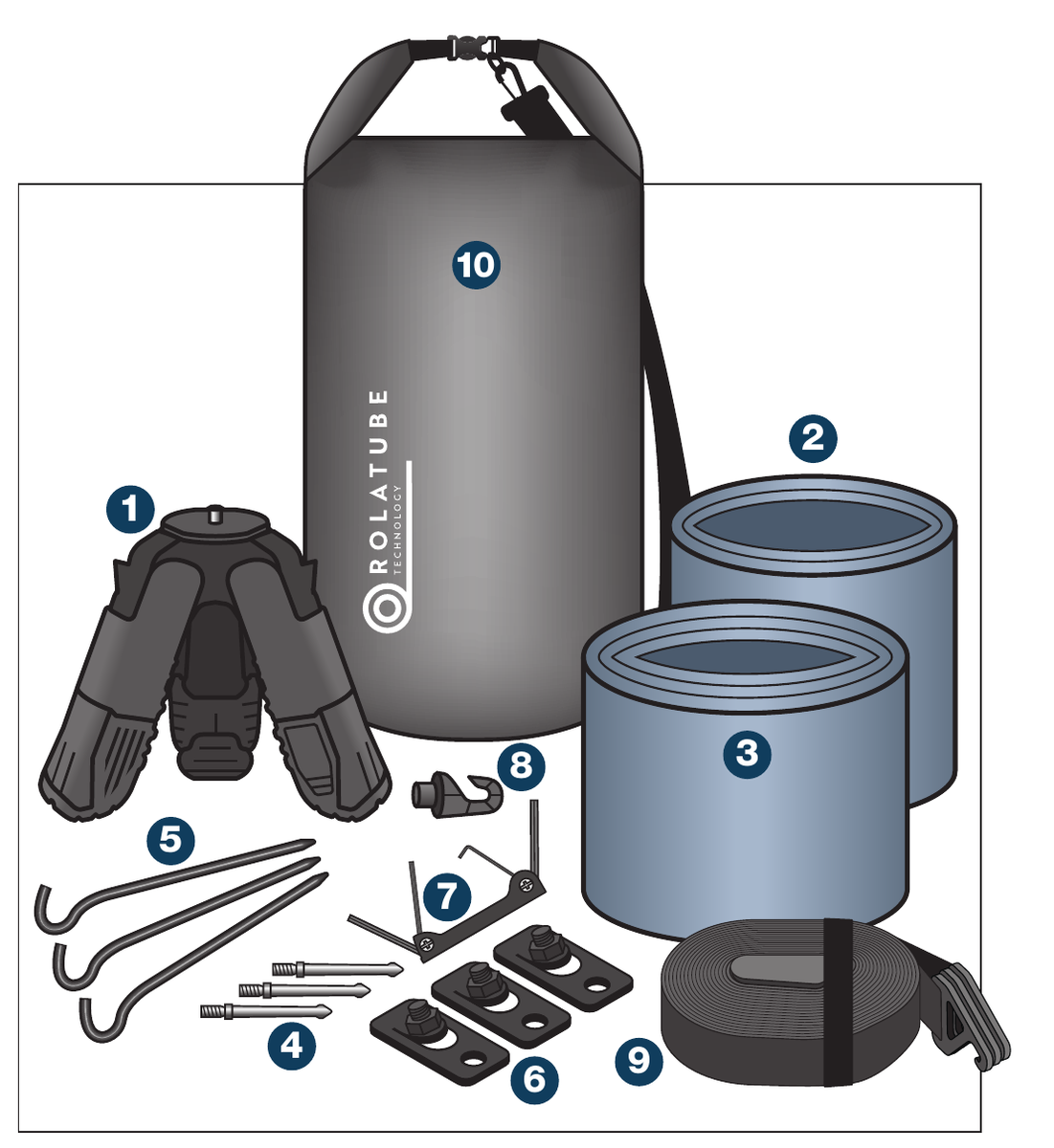
| Item | Description |
|---|---|
| 1 | Stubby tripod |
| 2 | 3 × 650mm legs |
| 3 | 3 × 1250mm legs |
| 4 | 3 × 65mm foot spikes |
| 5 | 3 × Pegs |
| 6 | 3 × Peg plates |
| 7 | 1 × Allen Key set |
| 8 | 1 × Hook |
| 9 | Leg Tie (Separate User Guide provided) * |
| 10 | Bag |
The systems are rated to the loads stated. The end user is responsible for ensuring the loads are securely fastened. Rolatube Technology does not accept liability or provide warranty for usage deviating from the enclosed instructions.
- Before deploying the tripod please read all warnings below.
- Avoid contact with heavy and sharp objects, in storage do not stack anything on top of Rolatubes.
- Do not use the tripod if there is visible damage.
- The end user must assess the suitability of the pegs provided for the intended deployment environment, and replace with more suitable products if necessary.
- Rolatube tripod systems are rated for wind speeds of up to 100kph (62 mph) when pegged to the ground. The maximum wind rating is based on the unloaded tripod correctly deployed with pegs or foot spikes. The end user or system integrator is responsible for ensuring the system is safe with the top load mounted.
- Top load limits are subject to the user assessing the ground conditions. If the feet slip then these safe load limits are significantly compromised and the pegs, spikes or leg ties should be used.
- Ensure the deployment site is as flat as possible and clear of any cables or equipment that represents an electric shock hazard.
- Do not deploy near power lines, in thunderstorms or winds exceeding 100kph (62mph).
- Do not exceed the rated top load of the tripod.
- Ensure any top load is securely fastened.
- Do not allow the tripod legs to bend.
- Ensure the deployment site is clear of any underground hazards before using pegs.
- If used, ensure pegs are secure for duration of deployment.
- Consideration must be given to the location of any cable from the top load to avoid trip hazards.
- Consideration must be given when deploying in proximity to an aircraft landing site for aircraft movement.
- Rolatube tripods are only designed to function with the top load in the vertical axis.
Follow the illustrated sequence for the mode you require. Load ratings shown in the illustrations: 40kg (88lb) at the 25° leg angle; 20kg (44lb) with 650mm legs at the 45° leg angle.
Prone/Platform Mode
Stubby tripod only (no legs). Deploy the stubby tripod from its roll, spread the legs to the 25° or 45° position, then fit and adjust the payload mount.

Sitting Mode
Stubby tripod with 3 × 650mm legs. Unroll the three 650mm legs, click each into the stubby tripod until it clicks home. Rated 40kg (88lb) at 25°; 20kg (44lb) at 45°.

Standing Mode
Stubby tripod with 3 × 1250mm legs. Unroll the three 1250mm legs, click each into the stubby tripod until it clicks home. Rated 40kg (88lb) at 25°; do not use the 45° leg angle in standing mode.

Storage
Release and remove the three legs, roll each leg back up, fold the stubby tripod and pack the system into the bag.

Connecting Foot Spikes
Remove the foot fastener with the Ø6mm Allen key, fit the foot spike and re-fasten.
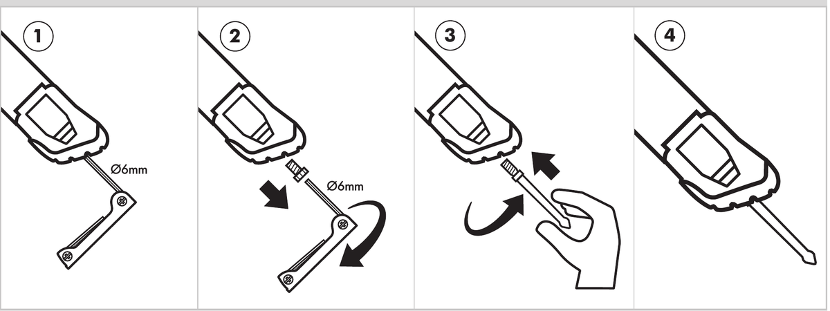
Connecting Peg Plates
Remove the foot fastener with the Ø6mm Allen key, fit the peg plate, secure the nut with the Ø7/32″ Allen key and re-fasten.

Attaching Hook
Insert the hook into the underside of the stubby tripod and twist to lock. The hook is rated for hanging loads up to 20kg (44lb).

+44 (0)1590 688019
enquiries@rolatube.com
RTL Materials Ltd trading as Rolatube Technology
130 Wellworthy Road, Ampress Park, Lymington SO41 8JY, UK
Registered in England & Wales No. 3332020 • VAT Reg 706 972 317
System 30: Industrial Compact Tripod (ICT)
Modular build-your-own compact tripod — for loads up to 40kg (88lb)


| No legs (Stubby configuration) | 650mm legs @ 25° | 1250mm legs @ 25° | 650mm legs @ 45°*i | |
|---|---|---|---|---|
| Max Top Load 1 | 40kg (88lb) | 40kg (88lb) | 40kg (88lb) | 20kg (44lb) |
| Maximum Payload Height | @25° 240mm (9.4″) @45° 220mm (8.6″) |
740mm (29.1″) | 1290mm (50.7″) | 590mm (23.2″) |
| Minimum Payload Height | @25° 150mm (5.9″) @45° 145mm (5.7″) |
650mm (25.5″) | 1200mm (47.2″) | 500mm (19.6″) |
| System Weight* | 1.32kg (2.9lb) 1.44kg (3.1lb) pegged 1.42kg (3.1lb) with spikes |
1.71kg (3.7lb) 1.83kg (4lb) pegged 1.81kg (3.9lb) with spikes |
2.06kg (4.5lb) 2.18kg (4.8lb) pegged 2.16kg (4.7lb) with spikes |
1.71kg (3.7lb) 1.83kg (4lb) pegged 1.81kg (3.9lb) with spikes |
| Total System Weight | 2.84kg (without pegs) |
| Packed Dimensions | 190mm wide × 200mm deep × 180mm tall (7.4″ × 7.8″ × 7″) |
| Packed Volume | 0.00684 m3 (0.24′3) |
| Payload Mount Design | 3/8 – 16 UNC male thread. Additional locking grub screw. |
| System Component Options |
1 × Stubby Tripod 3 × Peg Plates 3 × Pegs 3 × Foot Spikes 3 × 650mm legs 3 × 1250mm legs 1 × Allen Key set 1 × Hook 1 × Leg Tie 1 × Bag |
| Construct |
Head assembly: Aluminium and PC/ABS Peg plate: Aluminium with stainless steel fasteners Pegs: Aluminium Leg Body: PP-Glass Fibre Composite Foot Spikes: Stainless steel |
| Standard Leg Finish | Black |
*i 1250mm legs not recommended for use at 45°
Notes: 1 Top load limits are subject to the user assessing the ground conditions. If the feet slip then these safe load limits are significantly compromised and the pegs, spikes or leg tie should be used.
Build your ICT System from the components below
| Component | Rolatube Part Number | Qty |
|---|---|---|
| Stubby Tripod | 800-008000-IND | 1 |
| Peg Plate (including nut & bolt) | 800-008100 | 3 |
| Peg | 207-002009 | 3 |
| Foot Spike | 403-000142 | 3 |
| 650mm leg | 850-tripod 650 | 3 |
| 1250mm leg | 850-tripod 1250 | 3 |
| Allen Key set | 403-000128 | 1 |
| Hook | 650-000483 | 1 |
| Leg Tie* | 800-500052 | 1 |
| Bag | 502-003058 | 1 |
+44 (0)1590 688019
enquiries@rolatube.com • www.rolatube.com
RTL Materials Ltd trading as Rolatube Technology
130 Wellworthy Road, Ampress Park, Lymington SO41 8JY, UK
Registered in England & Wales No. 3332020 • VAT Reg 706 972 317